Exhaust gas muffler for internal combustion engines and deep drawing tool therefor

a technology for exhaust gas mufflers and internal combustion engines, which is applied to vehicle components, applications, instruments, etc., can solve the problems of not allowing for optimal utilization of sheet metal strips, and achieve the effect of improving acoustic performance and material saving

Active Publication Date: 2016-09-13
TENNECO GMBH
View PDF26 Cites 1 Cited by
  • Summary
  • Abstract
  • Description
  • Claims
  • Application Information

AI Technical Summary

Benefits of technology

[0004]The object of the invention is to design and arrange an exhaust gas muffler made of shaped shells and a deep drawing tool for the production of a shaped shell such as to ensure material savings and an improved acoustic performance.
[0005]According to the invention, this object is achieved by providing the inner contour KSi of the edge region BS of the shell with at least one corner region E1-E4 in addition to the box-like basic shape C, which corner region extends beyond the width B and the length L, thus being at least partly adapted to the outer contour KR of the edge region BR of the blank R that needs to be cut to size. This serves to achieve a more uniform overall shape of the edge region BR of the blank that needs to be cut off in order to form the inner and / or outer contour KSi, KSa of the shell, resulting in material savings. In addition, the overall volume of each shell can be increased by utilizing the volumes of these corners. If the volume is increased in this way, the width and / or length of the shell as a whole can be made smaller while the volume remains the same, thus achieving further material savings, in case the width of the shell is reduced, as described above, the sheet metal strip used for deep drawing or the relevant coil can also be narrower.
[0006]If said corner regions of the edge region BR of the blank are utilized, the inner and / or outer contour KSi and / or KSa of the shell or the edge region BS obtained also differ(s) from the usual box-like basic shape G, resulting in favourable resonance characteristics or a favourable acoustic performance.

Problems solved by technology

However, this design does not allow for optimum utilization of the sheet metal strips that are to be shaped.

Method used


Image

  • Exhaust gas muffler for internal combustion engines and deep drawing tool therefor
  • Exhaust gas muffler for internal combustion engines and deep drawing tool therefor
  • Exhaust gas muffler for internal combustion engines and deep drawing tool therefor

Examples


Embodiment Construction

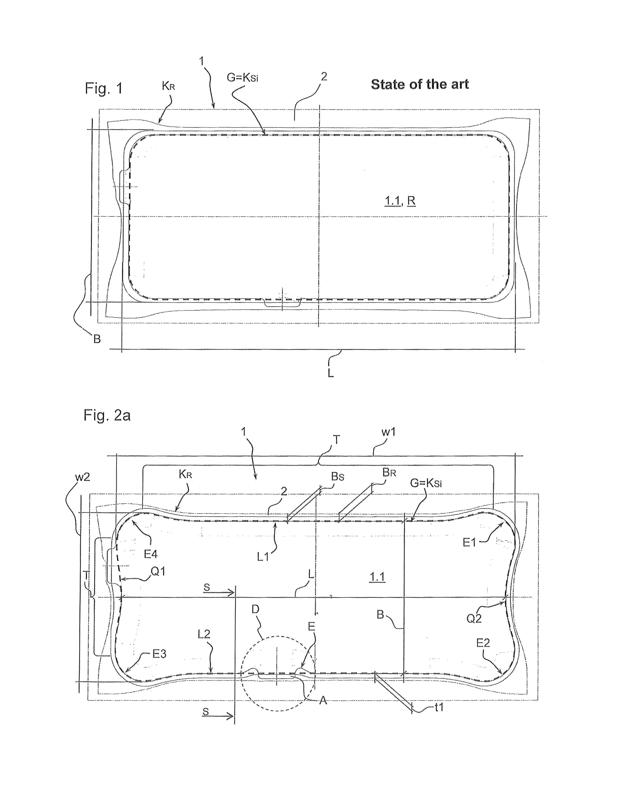
[0023]A first shell 1.1 of a shell muffler 1 according to the state of the art is formed by deep drawing of a sheet metal strip 2 that is rectangular in shape and is provided based on a sheet metal coil. First, a so-called blank R is obtained by deep drawing of a desired contour KS of the shell 1.1 with a basic shape G that is box-like, i.e. rectangular with rounded corners, according to FIG. 1; the edge of said blank has a contour KR differing from the rectangular shape of the sheet metal strip 2 on the one hand and from the desired box-shaped contour KS of the shell 1.1 on the other. The contour KR of the blank R is also referred to as bone-shaped since the remaining edge that needs to be cut off in order to form the contour KS or the outer contour KSa of the shell 1.1 is much larger in the region of each corner than in the region between the corners.

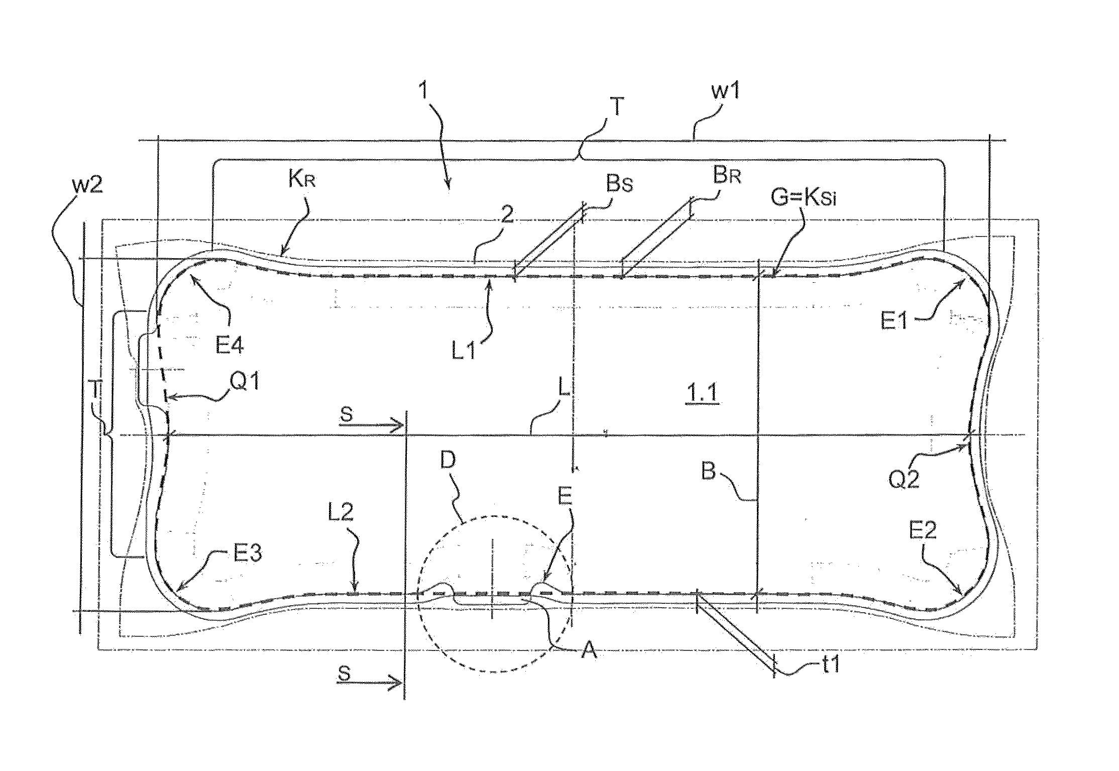
[0024]As shown in FIG. 2a, the contour KS according to the invention, i.e. the outer contour KSa and the inner contour KSi of the sh...


PUM

PropertyMeasurementUnit
widthaaaaaaaaaa
lengthaaaaaaaaaa
sizeaaaaaaaaaa

Abstract

A shell muffler for an internal combustion engine that is formed of a first shell and at least one second shell, which shells are connected at their respective edge regions BS so as to form the shell muffler, each edge region BS having a box-like inner contour KSi, which has four corner regions (E1)-(E4) and a width (B) and a length (L), and an outer contour KSa, and each shell being produced from a shell blank R, which is formed by deforming a sheet metal strip using a deep drawing tool having the shape of the shell, the blank R, after deforming, having an edge region BR with an outer contour KR, said edge region being removed at least partially after the blank R has been cut to size so as to form the outer contour KSa of the edge region BS of the shell. In addition to the box-like basic shape G, the inner contour KSi of the edge region BS of the shell has at least one corner region (E1-E4) which is expanded beyond the width B and the length L of the box-like basic shape (G) and is thus adapted at least partially to the contour KR of the edge region BR to be cut of the blank R.

Description

FIELD OF THE INVENTION[0001]The invention relates to a shell muffler for an internal combustion engine, formed of a first shell and at least one second shell, which are connected at their circumferential edge regions BS in order to form the shell muffler, each edge region BS having a box-shaped inner contour KSi, which has four corner regions E1-E4 and a width B and a length L, and an outer contour KSa, and each shell being produced from a shell blank R, which is formed by shaping a sheet metal strip by means of a deep drawing tool having the shape of the shell, the shaped blank R having an edge region BR, which has an outer contour KR and is cut off at least partly once the blank R has been cut to size in or to form an outer contour KSa of the edge region BS of the shell.BACKGROUND OF THE INVENTION[0002]An exhaust gas muffler that is formed of a pair of shaped shells is already known from CA 2,058,136, wherein an edge surface of the two shaped shells is folded in order to connect t...

Claims


Application Information

Patent Timeline
Patent Type & Authority Patents(United States)
IPC IPC(8): B21D22/26B21D51/18B21D22/20B21D53/88F01N13/18B21D22/22
CPCB21D22/20B21D22/26B21D51/18B21D53/88F01N13/1872B21D22/22F01N13/1861F01N13/1888F01N13/1894
Inventor SCHROER, KLAUS
Owner TENNECO GMBH
Why Eureka
Try Eureka