

Hybrid wastewater treatment
- Summary
- Abstract
- Description
- Claims
- Application Information
AI Technical Summary
Benefits of technology
Problems solved by technology
Method used
Image

Examples
Embodiment Construction
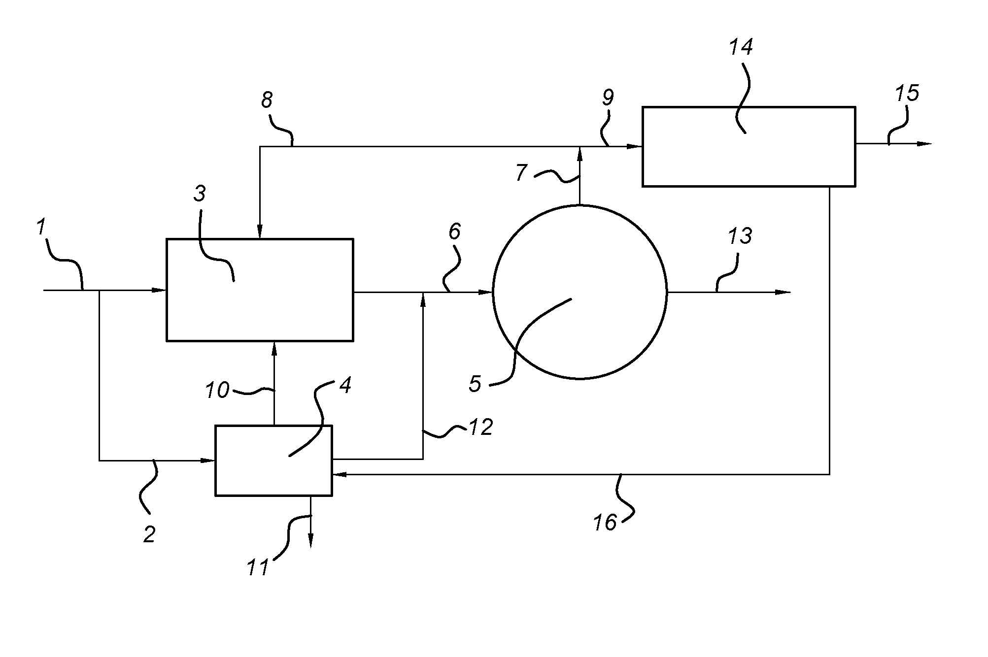
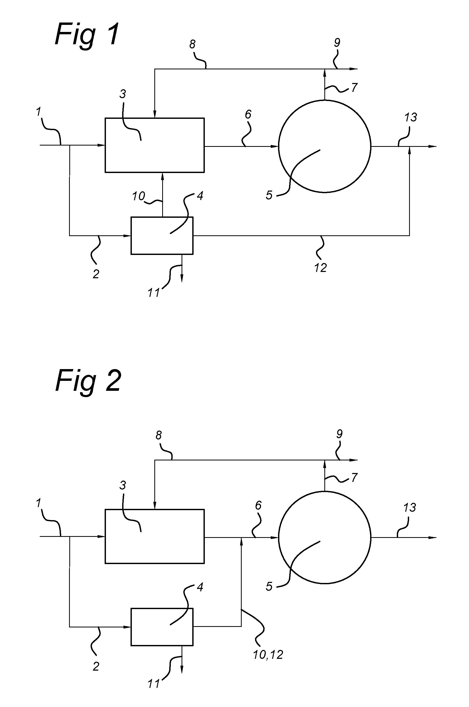
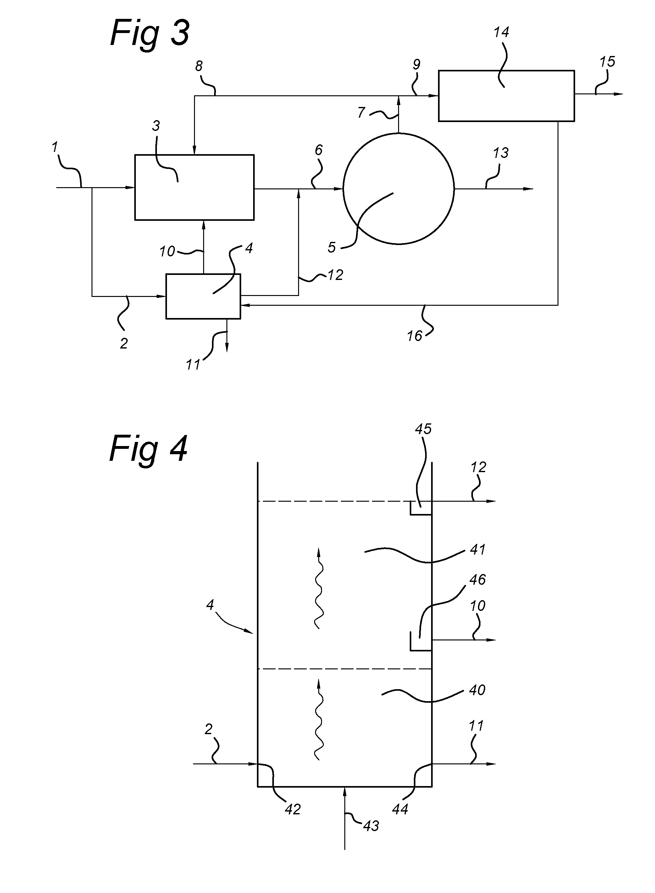
[0021]The invention thus provides a wastewater treatment process comprising subjecting a part of a wastewater supply to an activated sludge process using floc-like aerobic biomass, and feeding part of the wastewater to a granular biomass process using aerobic granular biomass, wherein part of the biomass, i.e. the waste biomass and suspended solids, issuing from the granular biomass process is fed to the activated sludge process.
[0022]The activated sludge process (CAS system) and the granular biomass process (AGB reactors) are run in parallel, meaning that the main wastewater stream is split into a stream subjected to the CAS system and a stream subjected to the AGB reactor(s), and the split streams are not substantially intermixed during the treatment process, other than in low amounts accompanying biomass transfer from the AGB system to the CAS system. The parallel setup is described in more detail here below. The part of the biomass from the granular biomass process that is fed t...
PUM
 Abstract
Description
Claims
Application Information