Method and device in nodes used for wireless communication

Pending Publication Date: 2022-05-19
SHANGHAI LANGHUA COMM TECH CO LTD
View PDF0 Cites 0 Cited by
  • Summary
  • Abstract
  • Description
  • Claims
  • Application Information

AI Technical Summary

Benefits of technology

[0005]In NR Release-15 system, a UE will only transmit Uplink Control Information (UCI) comprising a Hybrid Automatic Repeat reQuest Acknowledgement (HARQ-ACK) in a slot, and when a slot needs to feed back HARQ-ACKs of a plurality of PDSCHs, the UE will multiplex the corresponding plurality of HARQ-ACKs into a PUCCH or PUSCH. In the URLLC, time-domain resources occupied by a PUCCH will be narrower than time-domain resources occ

Problems solved by technology

Such a solution will cause the UCI fed back first in the URLLC to wait for the UCI fed back later to be transmitted together, which will introduce extra delay; and meanwhile, configuration of the PUCCH resour

Method used


Image

  • Method and device in nodes used for wireless communication
  • Method and device in nodes used for wireless communication
  • Method and device in nodes used for wireless communication

Examples


embodiment 1

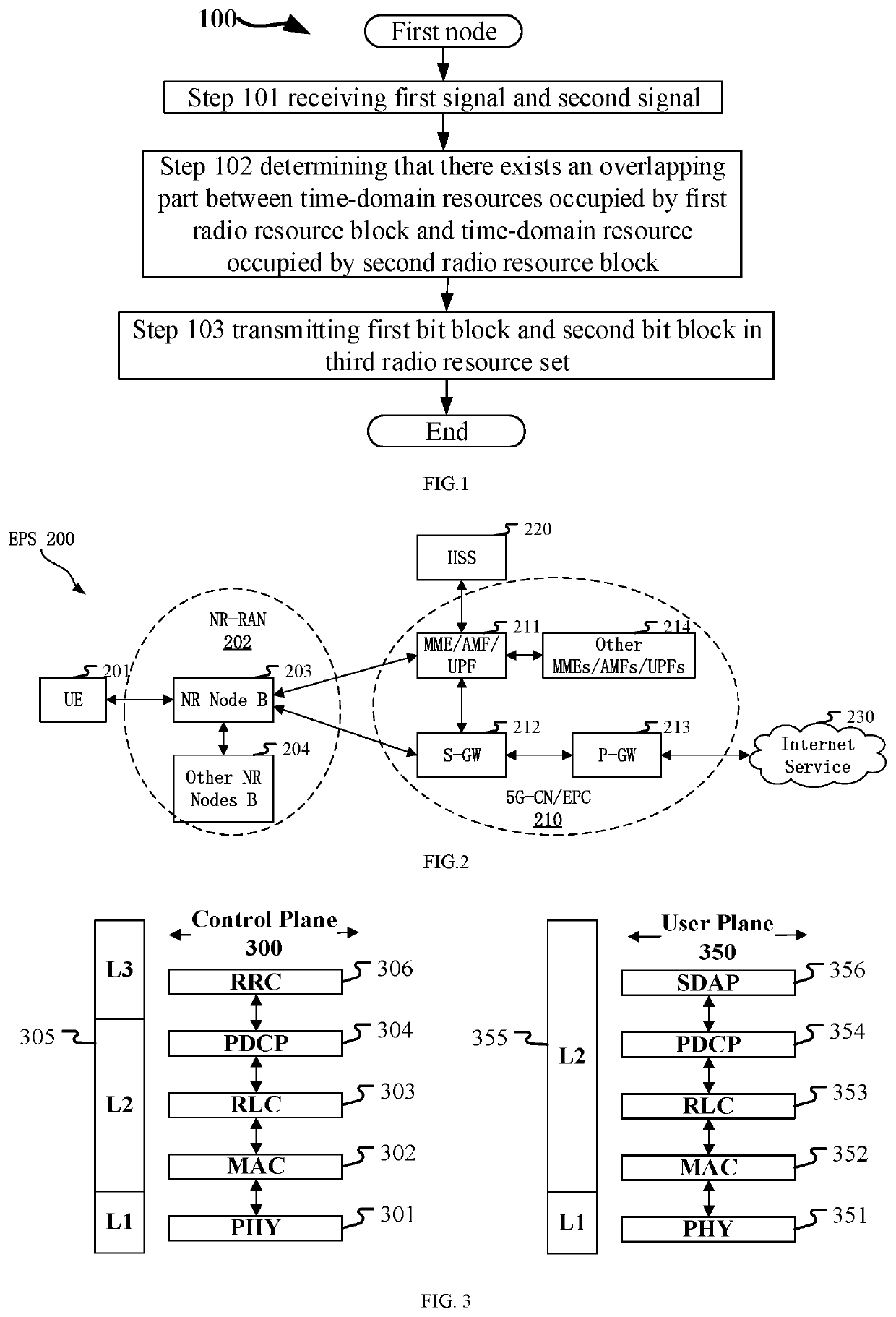
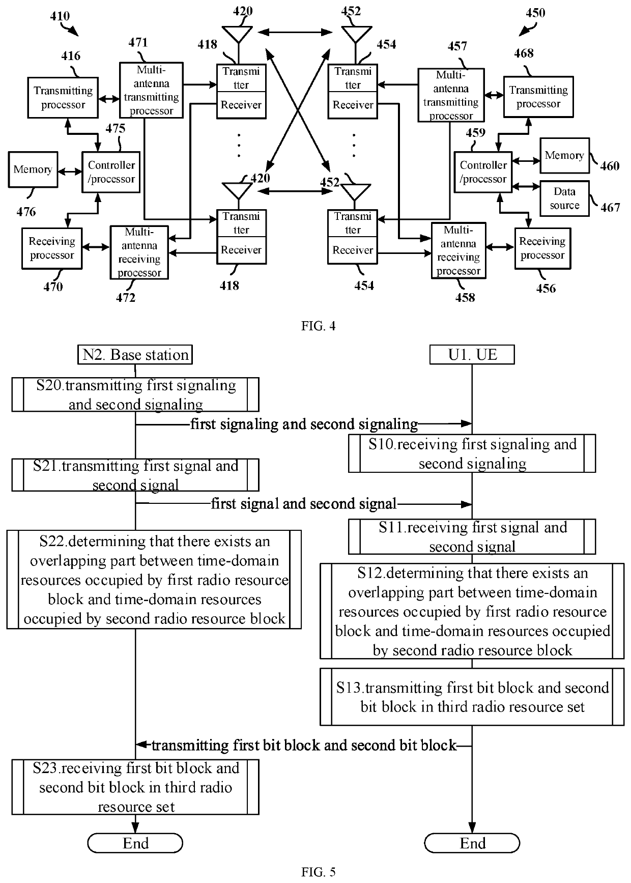
[0067]Embodiment 1 illustrates a flowchart of the processing of a first node, as shown in FIG. 1. In step 100 illustrated by FIG. 1, each box represents a step. In Embodiment 1, a first node in the present disclosure receives first signal and a second signal in step S101; determines that there exists an overlapping part in time domain between time-domain resources occupied by a first radio resource block and time-domain resources occupied by a second radio resource block in step S102; and transmits a first bit block and a second bit block in a third radio resource set in step S103.

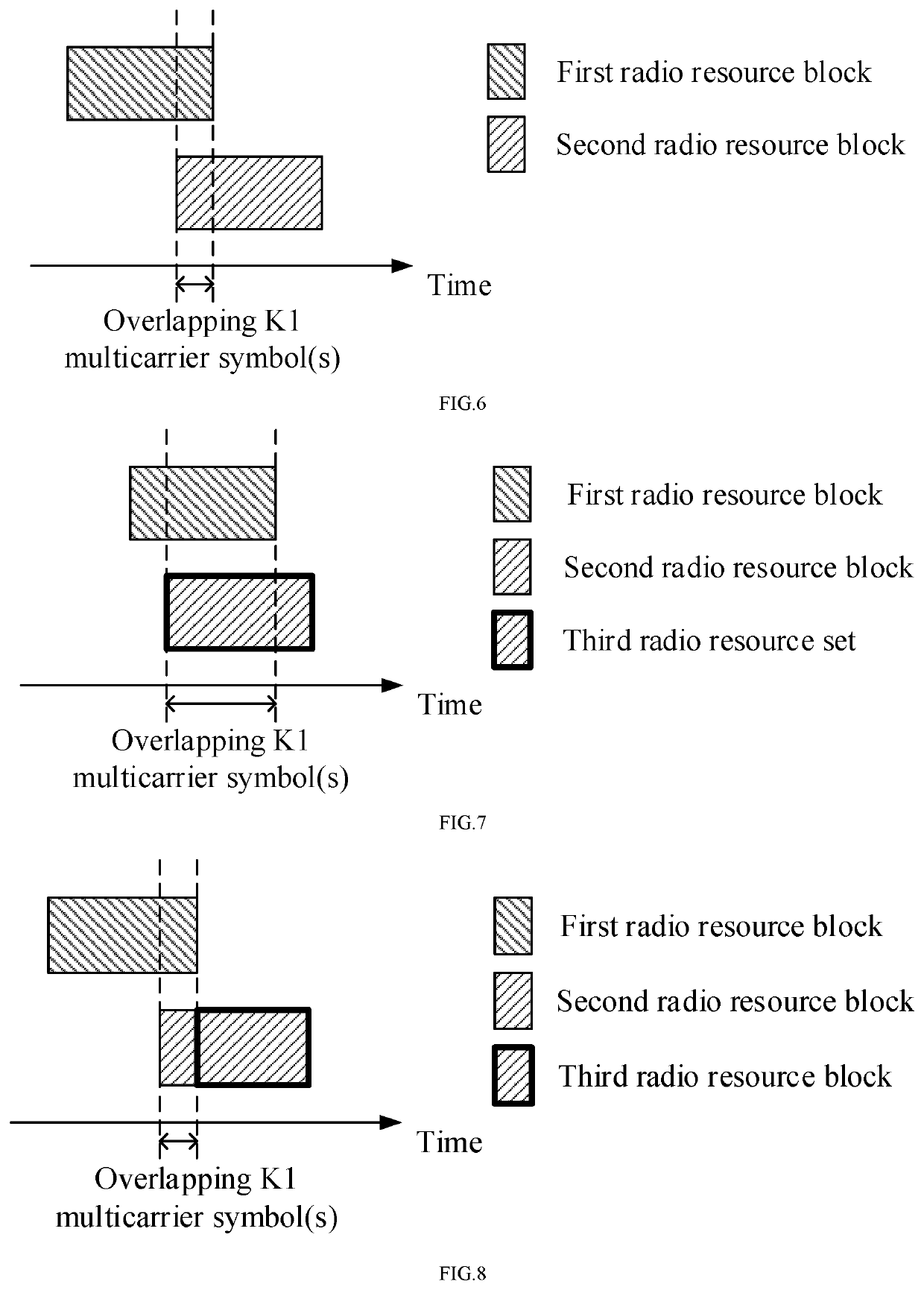
[0068]In embodiment 1, the first bit block and the second bit block are respectively used to indicate whether a bit block carried by the first signal and a bit block carried by the second signal are correctly received; the first radio resource block and the second radio resource block are respectively reserved for transmitting the first bit block and the second bit block; the overlapping part of the first ...

embodiment 2

[0114]Embodiment 2 illustrates a schematic diagram of a network architecture, as shown in FIG. 2.

[0115]FIG. 2 illustrates a network architecture 200 of 5G NR, Long-Term Evolution (LTE) and Long-Term Evolution Advanced (LTE-A) systems. The NR 5G or LIE network architecture 200 may be called an Evolved Packet System (EPS) 200 or other appropriate terms. The EPS 200 may comprise one or more UEs 201, an NG-RAN 202, an Evolved Packet Core / 5G-Core Network (EPC / 5G-CN) 210, a Home Subscriber Server (HSS) 220 and an Internet Service 230. The EPS 200 may be interconnected with other access networks. For simple description, the entities / interfaces are not shown. As shown in FIG. 2, the EPS 200 provides packet switching services. Those skilled in the art will readily understand that various concepts presented throughout the present disclosure can be extended to networks providing circuit switching services or other cellular networks. The NG-RAN 202 comprises an NR node B (gNB) 203 and other gNB...

embodiment 3

[0129]Embodiment 3 illustrates a schematic diagram of an example of a radio protocol architecture of a user plane and a control plane according to one embodiment of the present disclosure, as shown in FIG. 3. FIG. 3 is a schematic diagram illustrating an embodiment of a radio protocol architecture of a user plane 350 and a control plane 300. In FIG. 3, the radio protocol architecture for a first communication node (UE, gNB or a RSU in V2X) and a second communication node (gNB, UE or a RSU in V2X), or between two UEs is represented by three layers, which are a layer 1, a layer 2 and a layer 3, respectively. The layer 1 (L1) is the lowest layer and performs signal processing functions of various PHY layers. The L1 is called PHY 301 in the present disclosure. The layer 2 (L2) 305 is above the PHY 301, and is in charge of a link between a first communication node and a second communication node, as well as two UEs via the PHY 301. L2 305 comprises a Medium Access Control (MAC) sublayer ...


PUM


Abstract

The present disclosure provides a method and device in a node used for wireless communications. A first node first receives a first signal and a second signal; determines that there exists an overlapping between a first radio resource block and a second radio resource block in time domain; then transmits a first bit block and a second bit block in a third radio resource set; the first bit block and the second bit block are respectively used to indicate whether the first signal and the second signal are correctly received; the first radio resource block and the second radio resource block are respectively reserved for transmitting the first bit block and the second bit block. The application determines different transmission methods of uplink control information according to a value of K1, which reduces the impact caused by the conflict and improves the uplink transmission performance.

Description

CROSS REFERENCE TO RELATED APPLICATIONS[0001]This application is the continuation of International Patent Application No. PCT / CN2020 / 104729, filed on Jul. 27, 2020, which claims the priority benefit of Chinese Patent Application No. 201910724481.3, filed on Aug. 7, 2019, the full disclosure of which is incorporated herein by reference.BACKGROUNDTechnical Field[0002]The present disclosure relates to transmission methods and devices in wireless communication systems, and in particular to a method and device for transmitting uplink control information of a radio signal in a wireless communication system.Related Art[0003]In 5G system, in order to support more demanding Ultra Reliable and Low Latency Communication (URLLC) services, for example, with higher reliability (e.g., a target BLER is 10{circumflex over ( )}-6) and with lower delay (e.g., 0.5-1 ms), a study item (SI) of URLLC advancement in New Radio (NR) Release 16 was approved at 3rd Generation Partner Project (3GPP) Radio Acces...

Claims


Application Information

Patent Timeline
IPC IPC(8): H04W72/04H04W28/26H04L1/00
CPCH04W72/0413H04L1/0003H04W28/26H04W72/0446H04L5/0053H04W72/20H04L5/0091H04L5/0005H04W72/21
Inventor JIANG, QIZHANG, XIAOBO
Owner SHANGHAI LANGHUA COMM TECH CO LTD
Why Eureka
Try Eureka