
Signal device with indirect lighting signal

Inactive Publication Date: 2015-11-26
WHITE STAGG
View PDF4 Cites 32 Cited by
  • Summary
  • Abstract
  • Description
  • Claims
  • Application Information

AI Technical Summary

Benefits of technology

The present invention is for a signal device that includes a housing and a circuit board with LEDs. The LEDs can be positioned close to the outer edge of the circuit board or spaced apart from each other. The signal device can also include a smoke detecting device, a severe weather warning device, and a carbon monoxide detecting device. The LEDs can also be positioned in close proximity to the outer edge of the module. The signal device can also include at least two smoke detecting devices, a severe weather warning device, and a carbon monoxide detecting device. The housing may have air gaps or a rib extending inward from a side of the air gap. The LEDs can be lit up when the smoke detecting device, severe weather warning device, or carbon monoxide detecting device detects a triggering event. The technical effects of this invention include improved detection and alarming of smoke, severe weather, and carbon monoxide, as well as improved lighting effects and aesthetic appearance.

Problems solved by technology

Because an ionization smoke detecting device has a relatively complicated structure having an inner ionization chamber and an outer ionization chamber as described above, the detecting device has problems that it takes a lot of time to assemble and set the detecting device and it is difficult to decrease the cost.
For example, in the case of the FET, the insulation between terminals may be deteriorated due to humidity or dust.
Therefore, it is troublesome to set the FET and intermediate electrode.
In the event of a fire, combustion particles entering the device's chamber disturb the quiescent state absorption characteristics, thereby producing IR scattering and causing IR energy to be detected by the photodiode.
The electrochemical and spectroscopic devices, whilst offering rapid response times, high resolution and high accuracy, are expensive and not suitable for domestic use.
Both types rely on a color change and could not be made “automatic” by the application of an electronic device the degree of color change.
These devices are not reusable.
However, their response to low CO concentrations tends to be poor and therefore constant monitoring is required and can only be used once and fail to provide audible warning signals.

Method used


Image

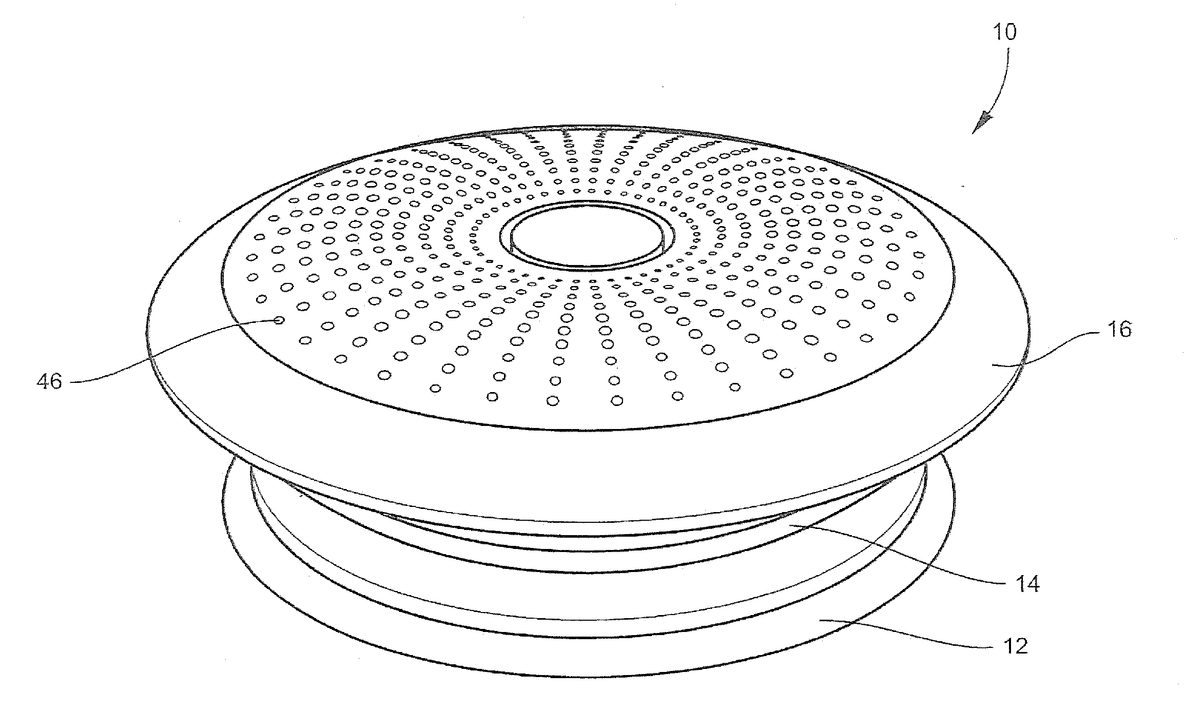
  • Signal device with indirect lighting signal
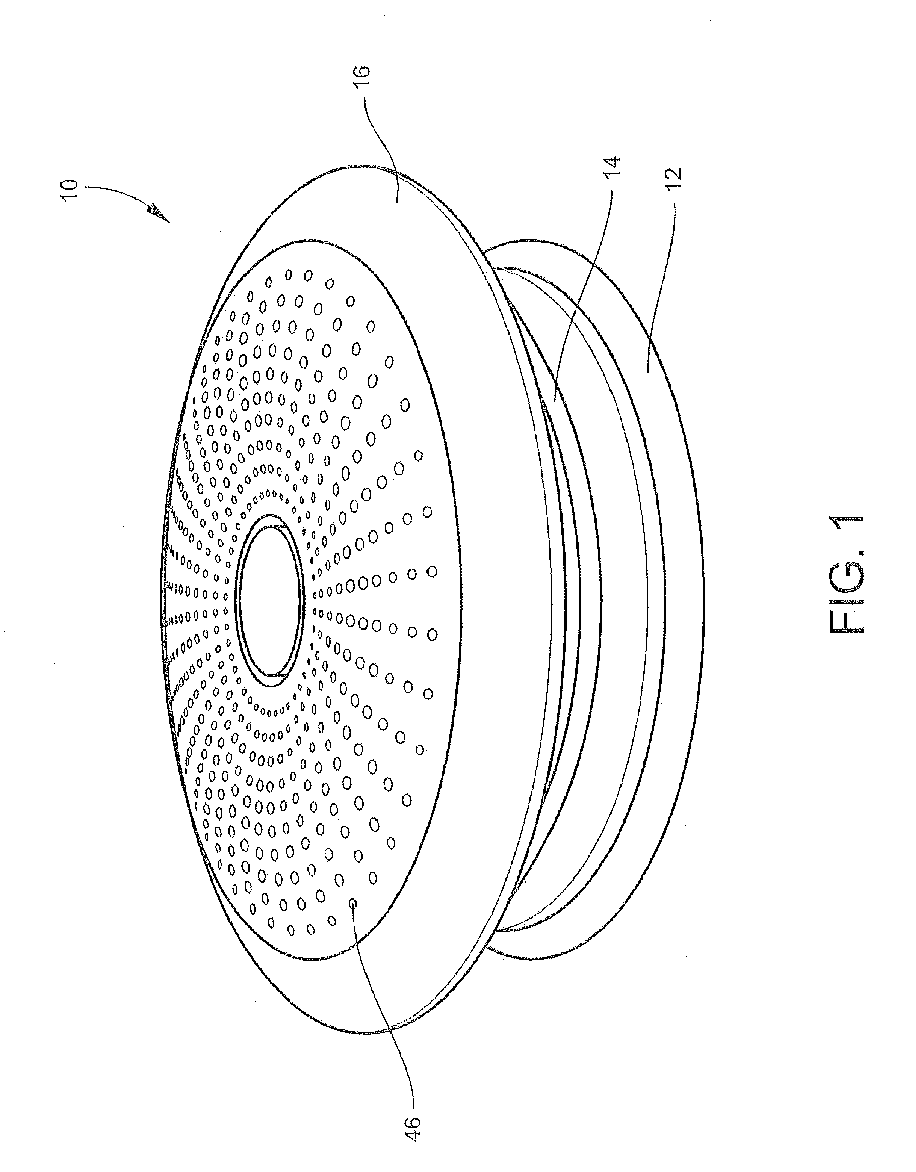
  • Signal device with indirect lighting signal
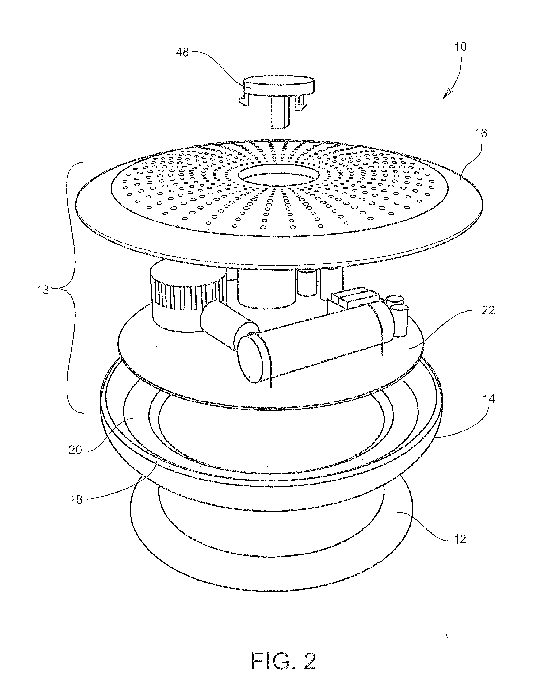
  • Signal device with indirect lighting signal

Examples


Embodiment Construction

[0034]The present invention may be understood more readily by reference to the following detailed description of the invention taken in connection with the accompanying drawing figures, which form a part of this disclosure. It is to be understood that this invention is not limited to the specific devices, methods, conditions or parameters described and / or shown herein, and that the terminology used herein is for the purpose of describing particular embodiments by way of example only and is not intended to be limiting of the claimed invention. Any and all patents and other publications identified in this specification are incorporated by reference as though fully set forth herein.

[0035]Also, as used in the specification including the appended claims, the singular forms “a,”“an,” and “the” include the plural, and reference to a particular numerical value includes at least that particular value, unless the context clearly dictates otherwise. Ranges may be expressed herein as from “abou...


PUM


Abstract

The present invention provides methods and systems for a signal device that includes at least one smoke detecting device, optionally a severe weather warning device, and optionally a carbon monoxide detecting device, which are housed within a housing comprising a top portion and a base. A circuit board having a top side and a bottom side that extends to an outer edge is also contained within the housing, and at least one LED is positioned in close proximity to the outer edge of the bottom side of the circuit board.

Description

CROSS REFERENCE TO RELATED PATENT APPLICATION[0001]The current application claims the benefit of the earlier priority filing date of the provisional application Ser. No. 61 / 989,121 that was filed on May 6, 2014.FIELD OF THE INVENTION[0002]The present invention relates generally to a signal device with an indirect lighting signal, and more generally relates to a warning signal device for detecting smoke and / or fire and / or carbon monoxide and / or severe weather and projecting color coded warning signals through indirect light.BACKGROUND OF THE INVENTION[0003]A smoke detecting device generally comprises, for example, a base secured to a ceiling or the like, a body removably set to the bottom of the base, and an outer cover for covering the face (bottom) opposite to the base of the detecting body.[0004]The detecting body comprises a circuit part comprising a printed circuit board on which electronic parts serving as a fire detecting circuit are mounted, a detecting part serving as a sens...

Claims


Application Information

Patent Timeline
IPC IPC(8): G08B5/36G08B17/10G08B21/10G08B21/14
CPCG08B5/36G08B21/10G08B17/10G08B21/14G08B1/08G08B17/00G08B17/113G08B27/00
Inventor STAGG, BRADLEY BENJAMIN
Owner WHITE STAGG
Features
  • Generate Ideas
  • Intellectual Property
  • Life Sciences
  • Materials
  • Tech Scout
  • Unparalleled Data Quality
  • Higher Quality Content
  • 60% Fewer Hallucinations
Learn More