
In-lane drive assist device

a technology of in-lane drive and assist device, which is applied in the direction of steering initiation, instruments, vessel construction, etc., can solve the problems of not being able to obtain the intended vehicle behavior, and the vehicle behavior variabl

Active Publication Date: 2015-12-03
NISSAN MOTOR CO LTD
View PDF14 Cites 28 Cited by
  • Summary
  • Abstract
  • Description
  • Claims
  • Application Information

AI Technical Summary

Benefits of technology

The patent text declares that the invention enables the vehicle to achieve the intended behavior regardless of the driver's ability to hold the steering wheel. This is achieved by a drive assist that is not affected by the driver's steering retention force.

Problems solved by technology

In the prior art described above, there is a problem that a turning angle obtained by increasing the assisting force fluctuates due to the steering retention force of the driver, resulting in a variation in the vehicle behavior and not being able to obtain the intended vehicle behavior.

Method used


Image

  • In-lane drive assist device
  • In-lane drive assist device
  • In-lane drive assist device

Examples


second embodiment

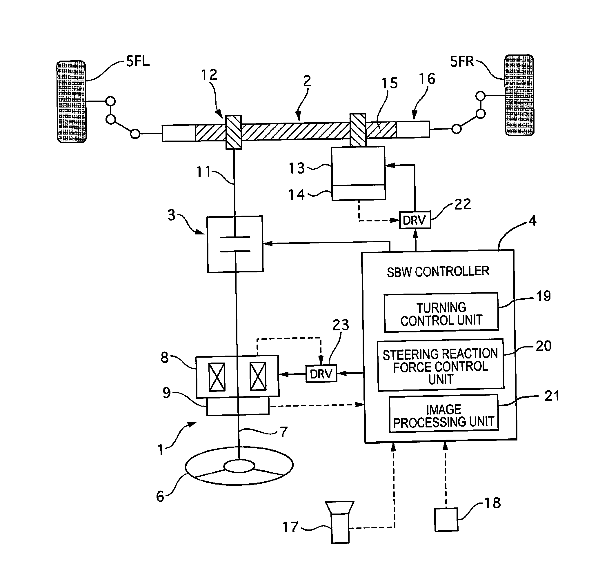
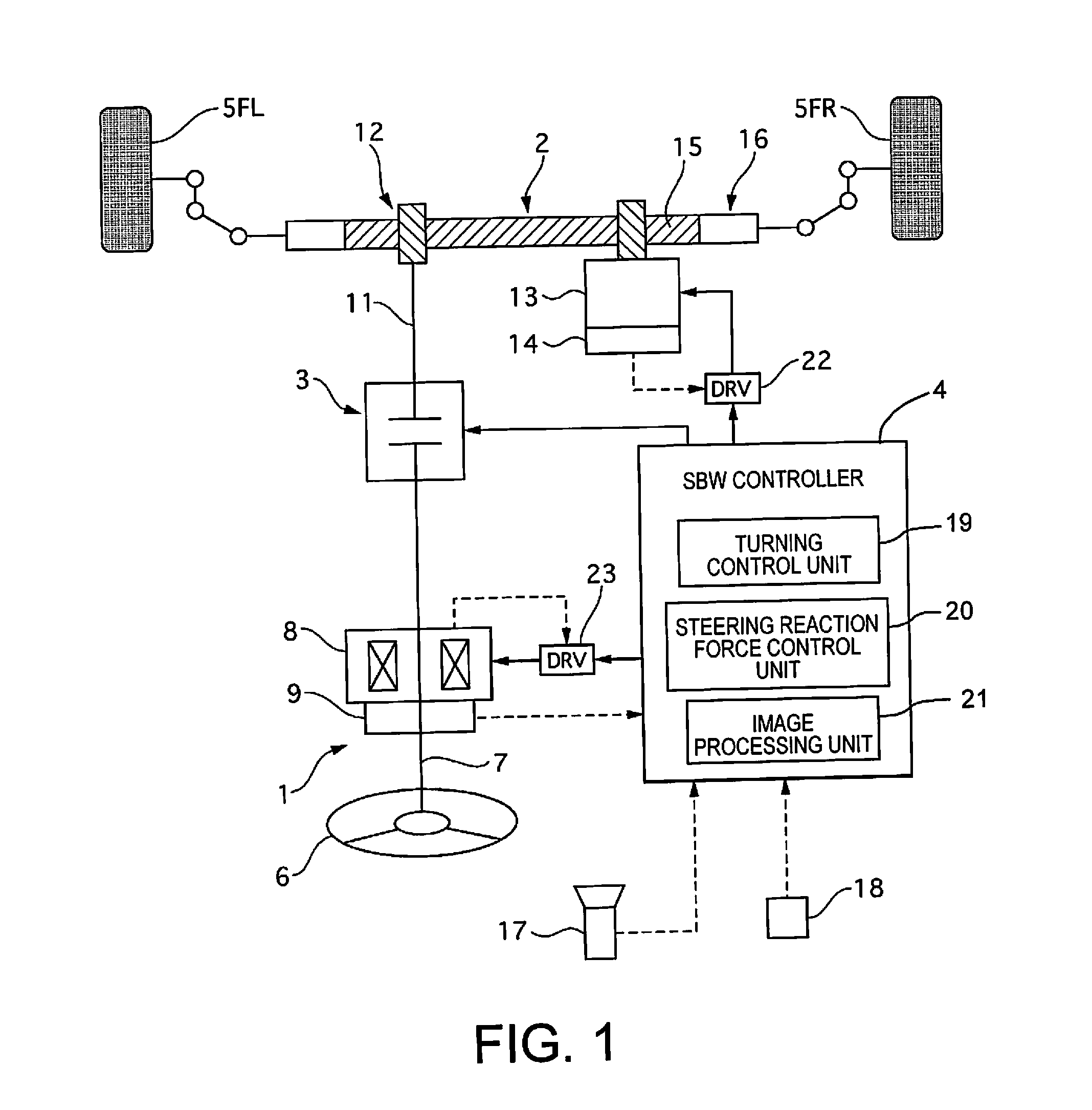
[0078]The steering device of the second embodiment is different from the first embodiment in the configuration of the steering reaction force control unit. FIG. 14 is a control block view of a steering reaction force control unit 50 of the second embodiment. Only the locations that differ from the first embodiment in FIG. 3 will be described. The lateral G sensor 51 detects the lateral acceleration (lateral G) of the vehicle. The yaw rate sensor 52 detects the yaw rate of the vehicle. The FB lateral force calculation unit 53 calculates a feedback (FB) tire lateral force based on the lateral G and the yaw rate, using a known two-wheel model.

[0079]The FF lateral force calculation unit 54 calculates a feed-forward (FF) tire lateral force by referencing a steering angle-lateral force conversion map representing the relationship between the steering angle and the tire lateral force per vehicle speed in a conventional steering device, which have been obtained by experimentation or other m...


PUM


Abstract

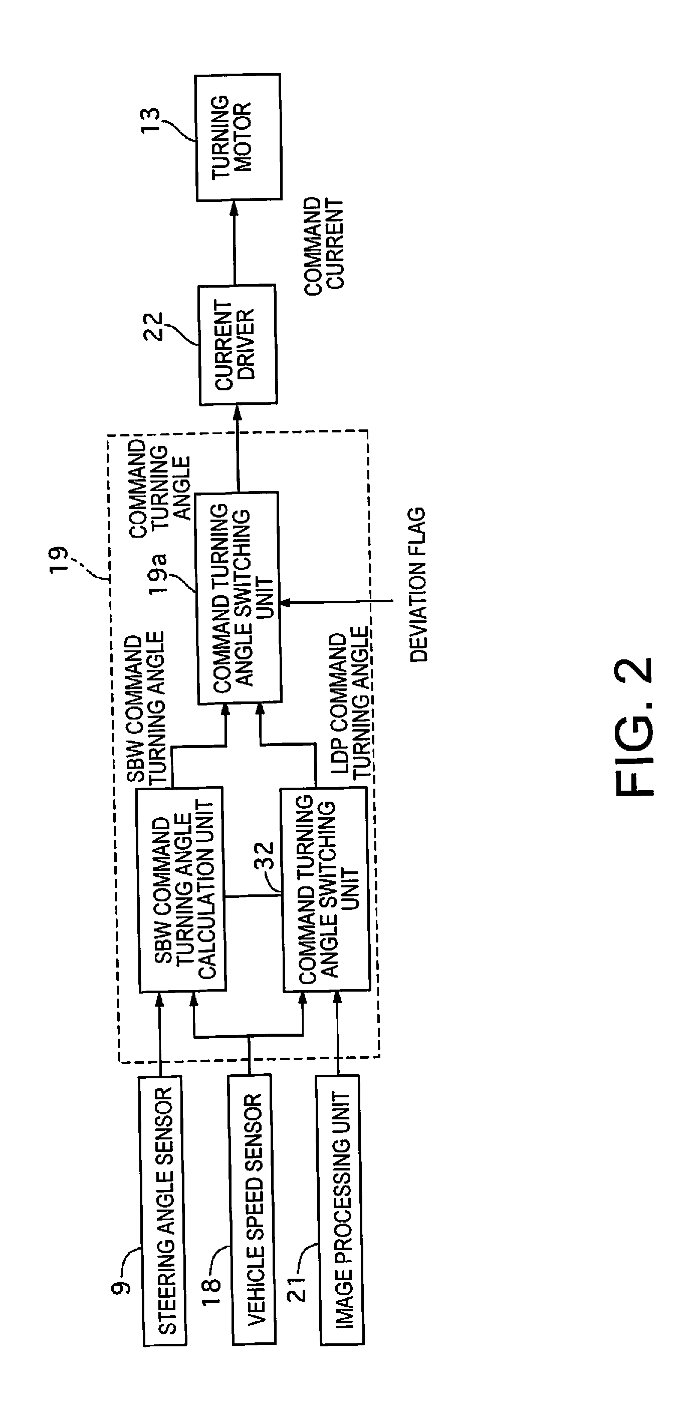
An in-lane drive assist device controls a turning amount of a turning unit that is mechanically detached from a steering unit-based on a steering amount of a steering unit when a lane deviation is determined to be absent. The in-lane drive assist device controls the turning amount based on a drive assist turning amount for generating a yaw moment to return a vehicle into a lane while the steering reaction force applied to the steering unit is controlled based on a target steering reaction force corresponding to a steering reaction force characteristic that is set so that a self-aligning torque increases as the steering reaction force increases when a lane deviation is determined to be present, and the steering reaction force characteristic is offset in a direction in which an absolute value of the steering reaction force increases as a lateral position of the vehicle approaches a white line.

Description

CROSS-REFERENCE TO RELATED APPLICATIONS[0001]This application is a U.S. National stage application of International Application No. PCT / JP2014 / 050061, filed Jan. 7, 2014, which claims priority to Japanese Patent Application No. 2013-002377 filed in Japan on Jan. 10, 2013.BACKGROUND[0002]1. Field of the Invention[0003]The present invention relates to an in-lane drive assist device.[0004]2. Background Information[0005]Japanese Laid-Open Patent Application No. 2006-248304 discloses a technique that determines the presence / absence of lane deviation with respect to a traveling lane, and, when a presence of lane deviation is determined, an assisting force of an electric power steering is increased in a direction to return the vehicle into the traveling lane.SUMMARY[0006]In the prior art described above, there is a problem that a turning angle obtained by increasing the assisting force fluctuates due to the steering retention force of the driver, resulting in a variation in the vehicle beh...

Claims


Application Information

Patent Timeline
IPC IPC(8): B62D15/02
CPCB62D15/025B62D6/003B62D6/008B62D6/00
Inventor TANIGUCHI, HIROKI
Owner NISSAN MOTOR CO LTD
Learn More