
Sheet feeding apparatus and image forming apparatus

a technology of feeding apparatus and forming apparatus, which is applied in the direction of thin material processing, instruments, and article separation, etc., can solve the problems of inability to meet the original need, difficult to reduce the widthwise length of the roller holder, and inability to close the manual feeding tray

Active Publication Date: 2015-12-03
CANON KK
View PDF1 Cites 5 Cited by
  • Summary
  • Abstract
  • Description
  • Claims
  • Application Information

AI Technical Summary

Benefits of technology

The invention is a sheet feeding apparatus that can hold and stack sheets, and feed them one by one. It includes a mechanism for adjusting the width of the sheets during storage and stacking, as well as a guide for directing the first adjustment member in a separate direction from the second adjustment member. This allows for easier handling and maintenance of the apparatus. The technical effects of this invention are improved precision and efficiency in sheet feeding, with enhanced user satisfaction and ease of use.

Problems solved by technology

However, if the side end regulating members are located at a position regulating a smallest size sheet at this time for example, there is a case when the side end regulating members abut against a roller holder holding the feed roller, thus disabling to close the manual feed tray.
Because the arrangement of storing the feed roller within the apparatus body by pushing the feed roller by the manual feed tray when the cover is closed is made to downsize the apparatus body in particular, this arrangement poses a problem that it cannot meet the original need.
It is noted that because the feed roller needs a certain width (widthwise length) in order to stably deliver the sheet without a skew, it is difficult to reduce a widthwise length of the roller holder.

Method used


Image

  • Sheet feeding apparatus and image forming apparatus
  • Sheet feeding apparatus and image forming apparatus
  • Sheet feeding apparatus and image forming apparatus

Examples


Embodiment Construction

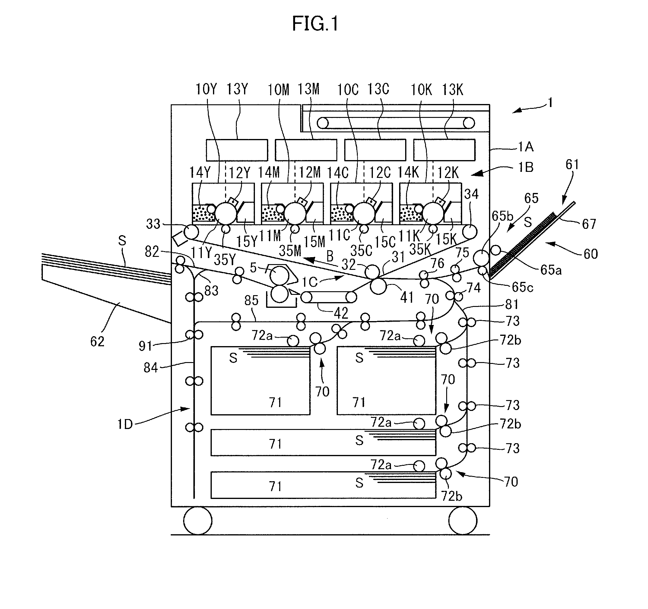
[0026]A mode for carrying out the invention will be described in detail with reference to the drawings. FIG. 1 is a schematic diagram illustrating a configuration of a color laser printer which is one exemplary image forming apparatus including a sheet feeding apparatus of an embodiment of the invention. In FIG. 1, the color laser printer includes a color laser printer body (referred to simply as a ‘printer body’ hereinafter) 1A, i.e., an image forming apparatus body. Provided within the printer body 1A are an image forming portion 1B forming an image on a sheet S, an intermediate transfer portion 1C, a fixing apparatus 5, a re-conveying portion 1D, a body sheet feeding apparatus 70 feeding the sheet S to the image forming portion 1B, a manual feeding apparatus 60, and others. It is noted that in the present embodiment, a front side of a sheet surface of FIG. 1 will be expressed as a front side of the printer body 1A and a rear side the sheet surface of FIG. 1 will be expressed as a...


PUM


Abstract

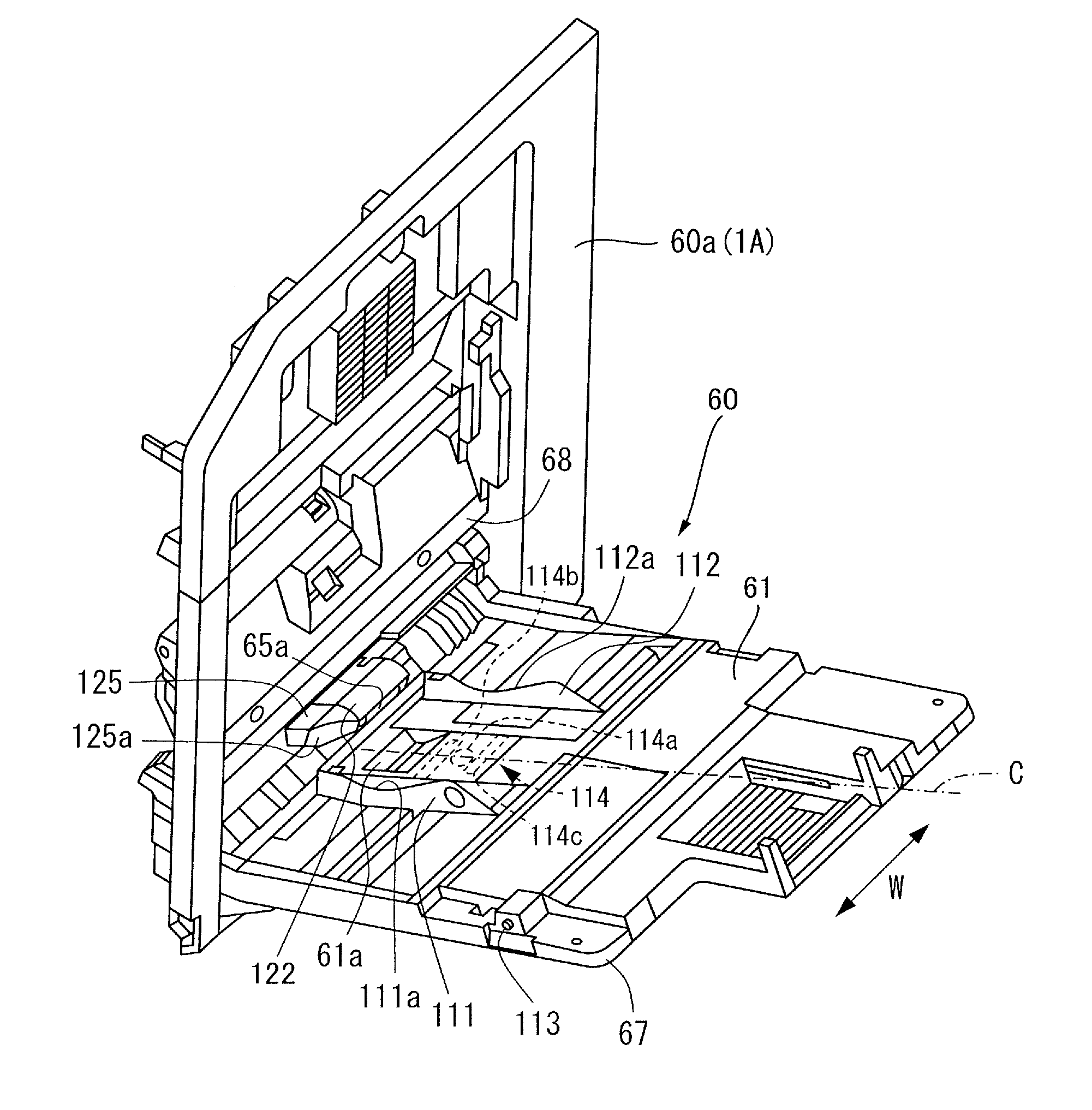
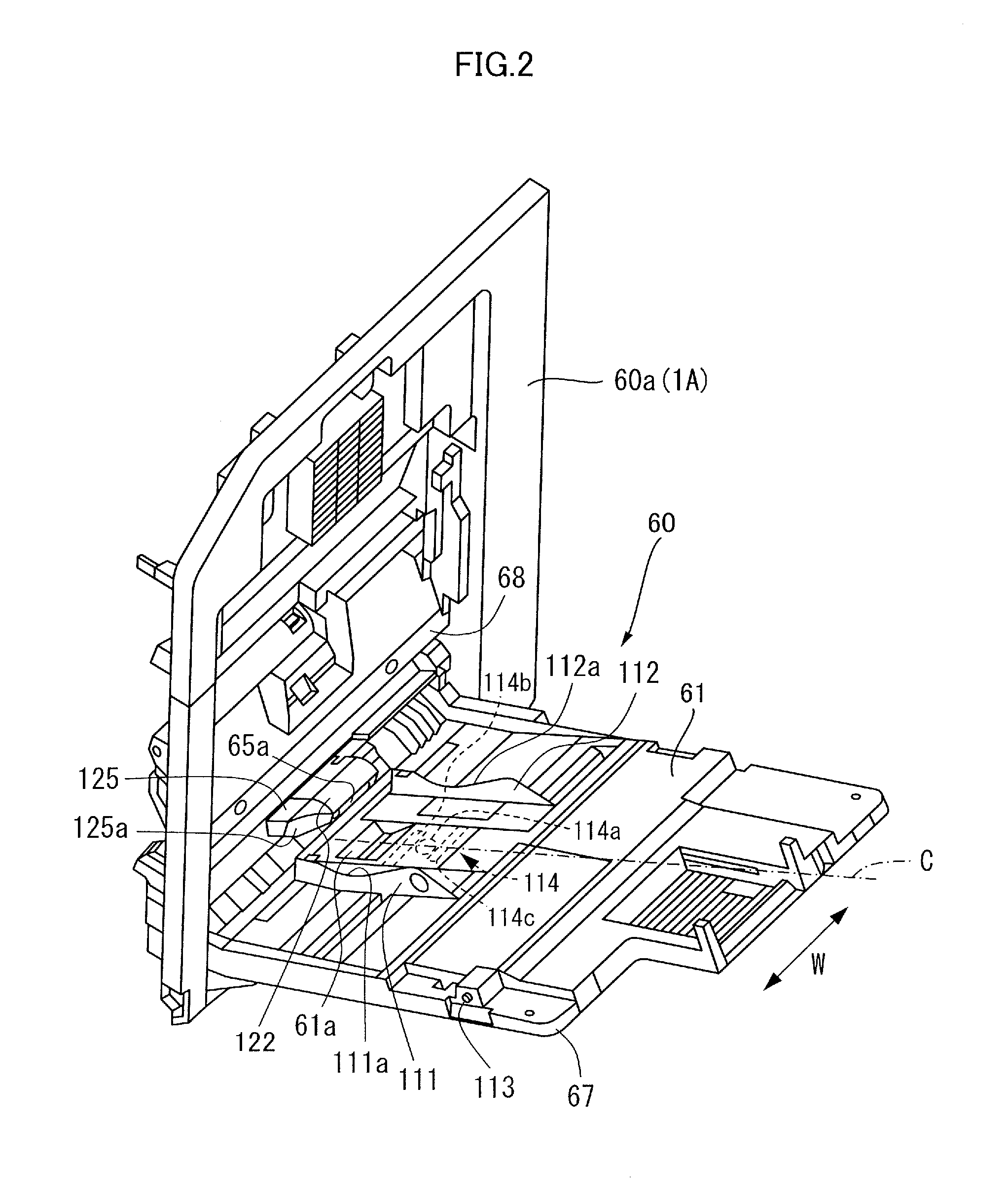
A sheet feeding apparatus includes an apparatus body, a manual feed tray, first and second regulating members regulating a width direction of a sheet, a feed portion feeding the sheet stacked on the manual feed tray, and a guide portion. The guide portion is provided at least at one of the apparatus body side and the first regulating member side and has an inclined surface that abuts against another member of the apparatus body and the first regulating member to guide the first regulating member in a direction separating widthwise from the second regulating member when the manual feed tray is moved from a sheet stacking position to a storage position.

Description

BACKGROUND OF THE INVENTION[0001]1. Field of the Invention[0002]The present invention relates to a sheet feeding apparatus and an image forming apparatus.[0003]2. Description of the Related Art[0004]Today, an image forming apparatus, i.e., a printer and a copier, configured to form an image on a sheet of paper (referred to simply as a ‘sheet’ hereinafter) supplied from a sheet feeding apparatus to an image forming portion spreads widely. Such image forming apparatus is demanded to be able to feed various kinds of sheets such as small size sheets, e.g., a postcard and an envelope, and sheets having various surface natures, e.g., a coated paper and an embossed paper, from the sheet feeding apparatus. Then, the image forming apparatus is arranged to stack these various kinds of sheets on a manual feed tray and to feed these sheets to an image forming portion by using the sheet feeding apparatus (referred to simply as a ‘manual feeding apparatus’ hereinafter) feeding a sheet stacked on ...

Claims


Application Information

Patent Timeline
IPC IPC(8): B65H1/08B65H3/34B65H5/06B65H1/04
CPCB65H1/08B65H5/06B65H3/34B65H1/04B65H2405/114B65H2405/324B65H2407/21B65H2511/12B65H2511/22G03G15/6502B65H2220/01B65H2220/04B65H1/00G03G15/00
Inventor KOGA, HIROTOSATO, KOKI
Owner CANON KK
Learn More