
Flooring underlayment and apparatus, flooring system and floor installation method using the same

a technology for flooring and underlayment, which is applied in the direction of flooring, synthetic resin layered products, transportation and packaging, etc., can solve the problems of not being able to adhere floor coverings such as vinyl flooring to a subfloor, and being laborious and messy

Inactive Publication Date: 2015-12-03
AFI LICENSING
View PDF9 Cites 19 Cited by
  • Summary
  • Abstract
  • Description
  • Claims
  • Application Information

AI Technical Summary

Benefits of technology

The invention is a flexible composite underlayment that can be used for a variety of floor systems. It includes a support layer, an adhesive layer, and a release layer. The underlayment can be positioned on a support surface and then peeled off to expose the adhesive layer. Floor panels can then be adhered to the underlayment in a desired pattern. The invention also includes an insulating layer on the lower surface of the support layer. The technical effects of the invention include improved sound insulation, flexibility, and ease of installation. Additionally, the invention allows for easy replacement of damaged floor panels without the need for additional adhesive.

Problems solved by technology

Typically, adhesives are applied at the installation location by employing a trowel to spread the adhesive on the underlayment, which is a labor intensive and often messy process.
Such techniques, however, are not suitable for adhering floor coverings such as vinyl flooring to a subfloor because it provides too much cushioning and not enough resiliency to protect the floor coverings, such as vinyl sheets, tiles, veneers, and high pressure laminate flooring from indent or deflection-type damage from concentrated loads.

Method used


Image

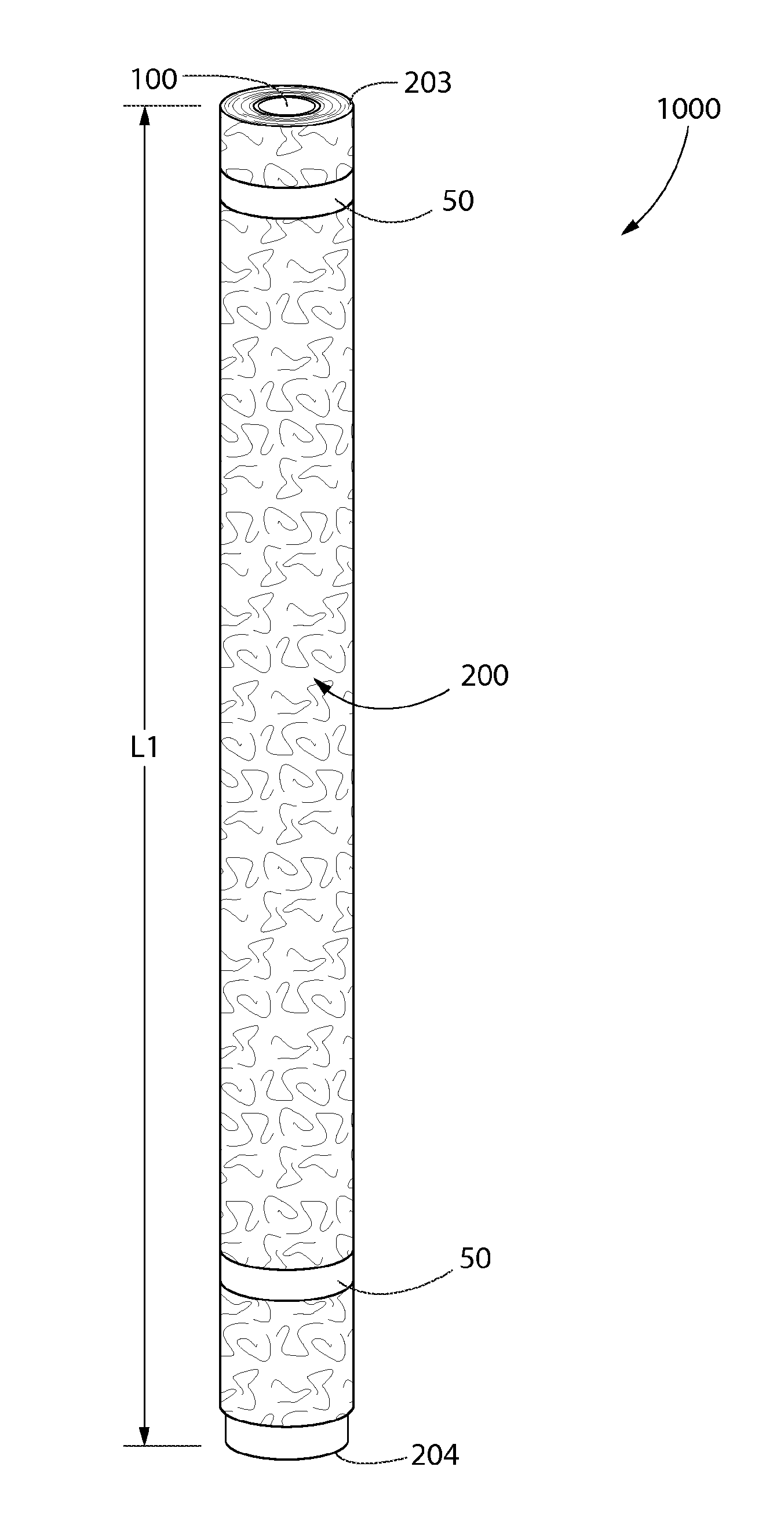
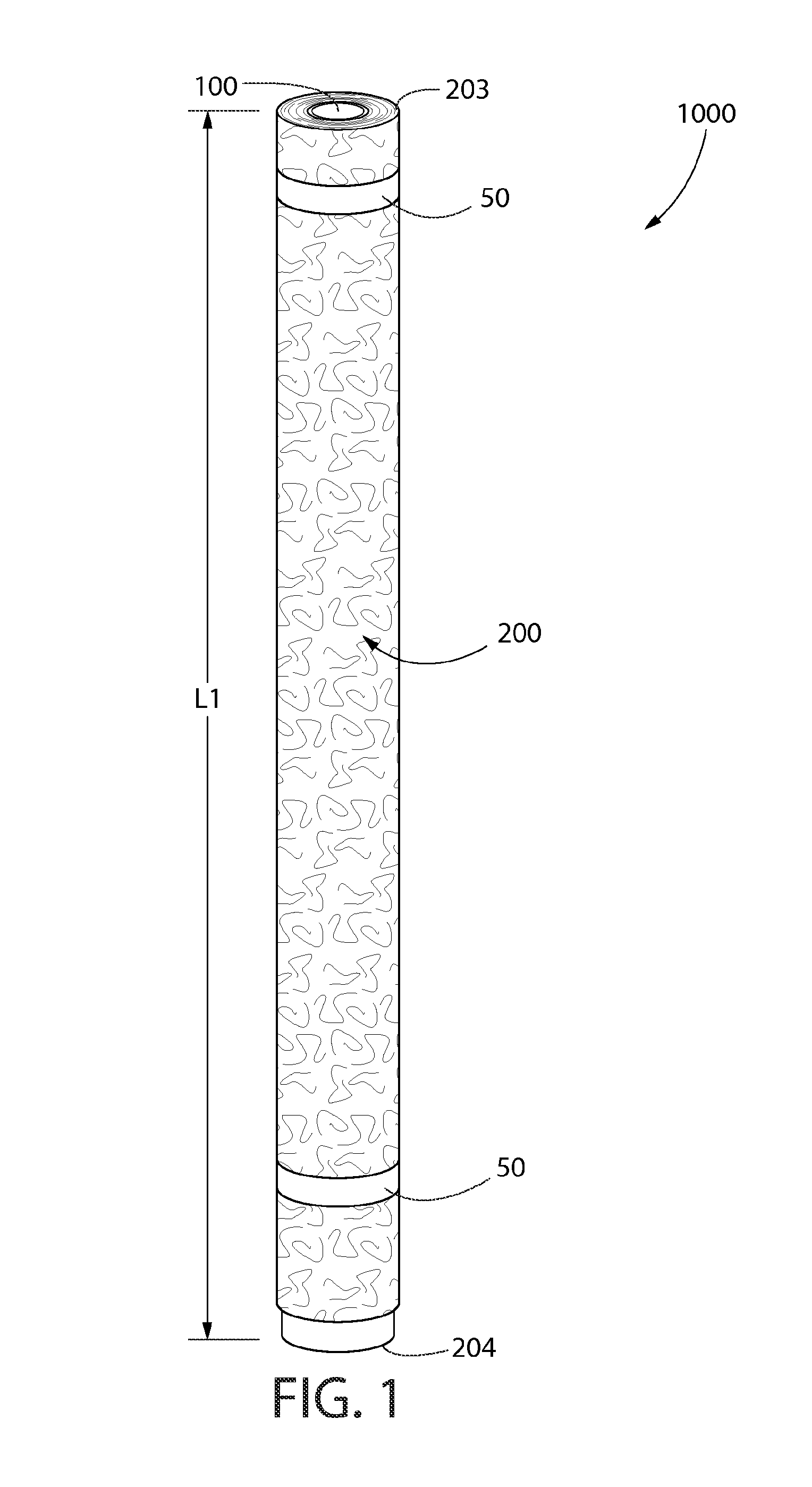
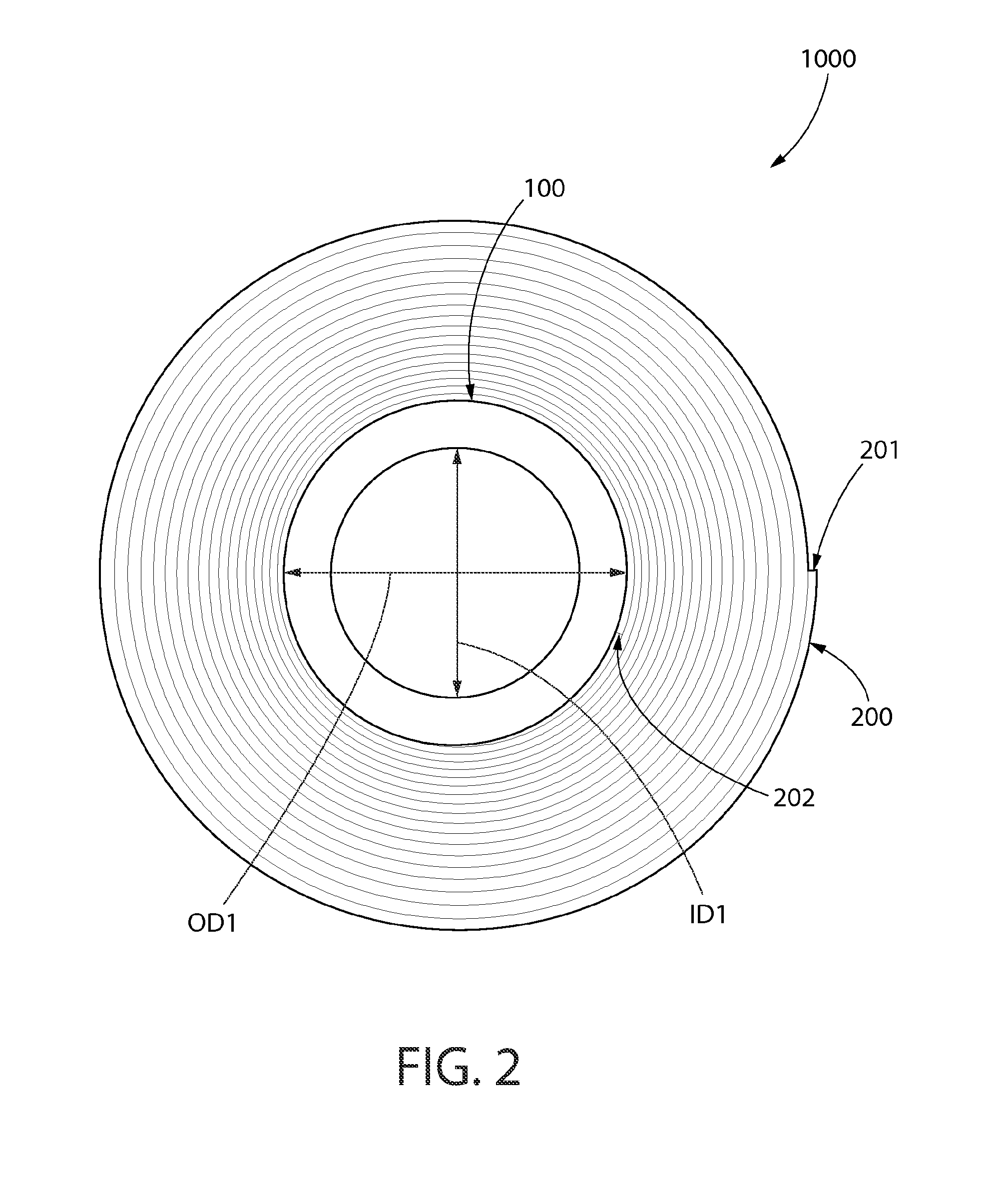
  • Flooring underlayment and apparatus, flooring system and floor installation method using the same
  • Flooring underlayment and apparatus, flooring system and floor installation method using the same
  • Flooring underlayment and apparatus, flooring system and floor installation method using the same

Examples


Embodiment Construction

[0025]The following description of the preferred embodiment(s) is merely exemplary in nature and is in no way intended to limit the invention, its application, or uses.

[0026]The description of illustrative embodiments according to principles of the present invention is intended to be read in connection with the accompanying drawings, which are to be considered part of the entire written description. In the description of embodiments of the invention disclosed herein, any reference to direction or orientation is merely intended for convenience of description and is not intended in any way to limit the scope of the present invention. Relative terms such as “lower,”“upper,”“horizontal.”“vertical,”“above,”“below,”“up,”“down,”“top” and “bottom” as well as derivative thereof (e.g., “horizontally,”“downwardly,”“upwardly,” etc.) should be construed to refer to the orientation as then described or as shown in the drawing under discussion. These relative terms are for convenience of descripti...


PUM

PropertyMeasurementUnit
diameteraaaaaaaaaa
lengthaaaaaaaaaa
outer diameteraaaaaaaaaa

Abstract

A flooring underlayment is disclosed that is particularly useful for the installation and formation of floating floor systems. In on embodiment, the invention can be an integral composite underlayment comprising: a flexible support layer having an upper surface and a lower surface; a pre-applied adhesive layer disposed on the upper surface of the flexible support layer, and a release layer coupled to disposed on the adhesive layer.

Description

CROSS-REFERENCE TO RELATED PATENT APPLICATIONS[0001]The present application claims the benefit of U.S. Provisional Patent Application Ser. No. 61 / 757,580, filed Jan. 28, 2013, the entirety of which is hereby incorporated by reference.FIELD OF THE INVENTION[0002]The present application relates generally to underlayments for floor coverings, and specifically to integral composite underlayments for floor coverings, such as floating floors, that include a release layer that can be removed to expose an adhesive layer.BACKGROUND OF THE INVENTION[0003]Surface coverings such as decorative finished floor coverings, often require an underlayment to be installed over a support surface, such as a structural wood or concrete subfloor. In traditional flooring systems, the underlayment is attached to the support surface by adhesives, nails, screws, staples or any combination thereof. In floating floor systems, which have become popular in recent years, the underlayment is simply positioned atop th...

Claims


Application Information

Patent Timeline
Patent Type & Authority Applications(United States)
IPC IPC(8): E04F15/18B32B5/02
CPCE04F15/182Y10T428/1476Y10T428/1419B32B5/022B32B27/12B32B27/20B32B27/40B32B2262/101E04F15/02155E04F15/166E04F15/187E04F15/203
Inventor PASTRANA, TONY T.
Owner AFI LICENSING
Learn More