Floating floor system, floor panel, and installation method for the same

a floating floor and floor panel technology, applied in the direction of flooring, covering/lining, construction, etc., can solve the problems of teeth not engaging slots and difficult installation/assembly process, and achieve the effect of simplifying the installation process, reducing the need for precision cutting of the floor panel, and balancing ease of installation

Inactive Publication Date: 2017-01-10
AFI LICENSING
View PDF16 Cites 20 Cited by
  • Summary
  • Abstract
  • Description
  • Claims
  • Application Information

AI Technical Summary

Benefits of technology

[0006]The present invention is directed to a floating floor system that utilizes a mechanical interlock system that allows longitudinally adjacent floor panels that are interlocked together to slide a sufficient distance relative to one another, while at the same time remaining interlocked in the transverse direction. In certain embodiments, this sliding may minimize and / or eliminate the need for precision cutting of the floor panels during the installation process, thereby simplifying the installation process. In certain embodiments, the mechanical interlock system may be configured such that the aforementioned sliding is facilitated while at the same time achieving a desired horizontal locking strength (HLS) per unit length of the floor panel that is greater than or equal to a predetermined lower threshold value. Thus, in one embodiment, the present invention is an optimized floor panel that balances ease of installation with sufficient HLS.

Problems solved by technology

One problem, with these existing mechanical interlocking systems is that the teeth are not easily alignable with the slots, thereby making the installation / assembly process difficult.
Additionally, in these existing floating floor systems, the teeth do not engage the slots even when aligned properly because of the straight 90 degree sides and clearance issues.

Method used


Image

  • Floating floor system, floor panel, and installation method for the same
  • Floating floor system, floor panel, and installation method for the same
  • Floating floor system, floor panel, and installation method for the same

Examples


Embodiment Construction

[0028]The following description of the preferred embodiment(s) is merely exemplary in nature and is in no way intended to limit the invention, its application, or uses. The description of illustrative embodiments according to principles of the present invention is intended to be read in connection with the accompanying drawings, which are to be considered part of the entire written description. Moreover, the features and benefits of the invention are illustrated by reference to the exemplified embodiments. Accordingly, the invention expressly should not be limited to such exemplary embodiments, which illustrate some possible non-limiting combinations of features that may exist alone or in other combinations of features; the scope of the invention being defined by the claims appended hereto.

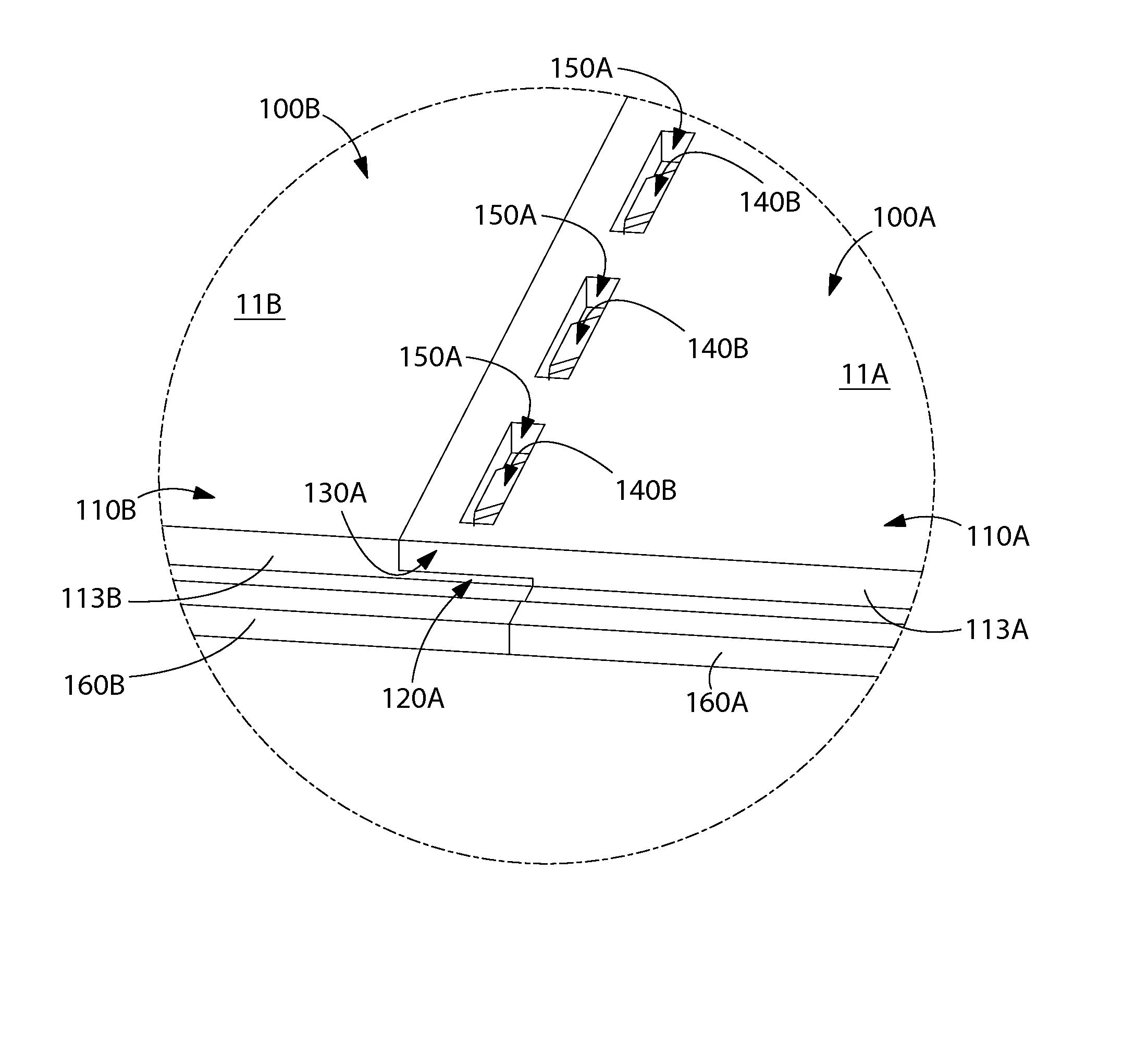
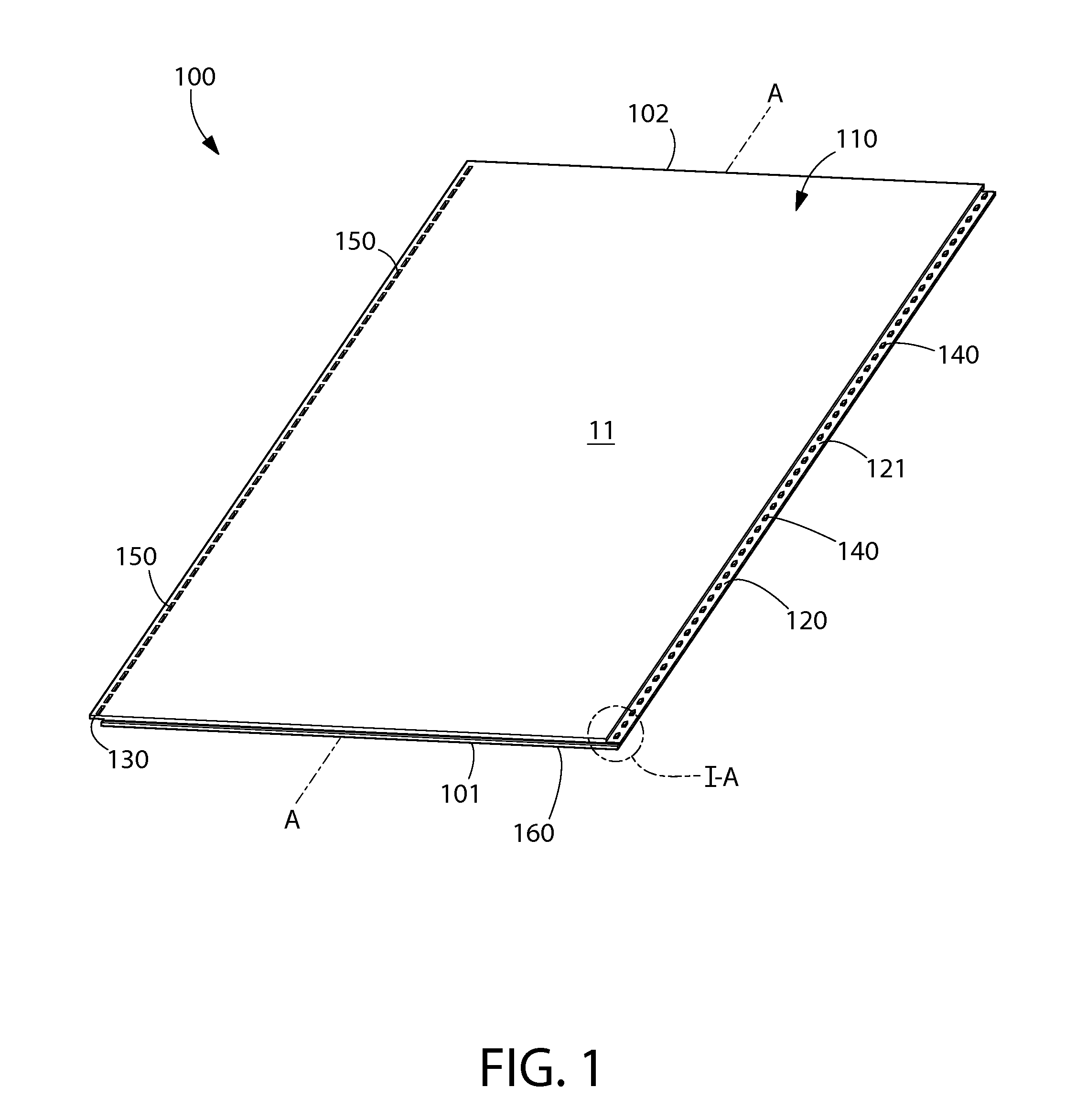
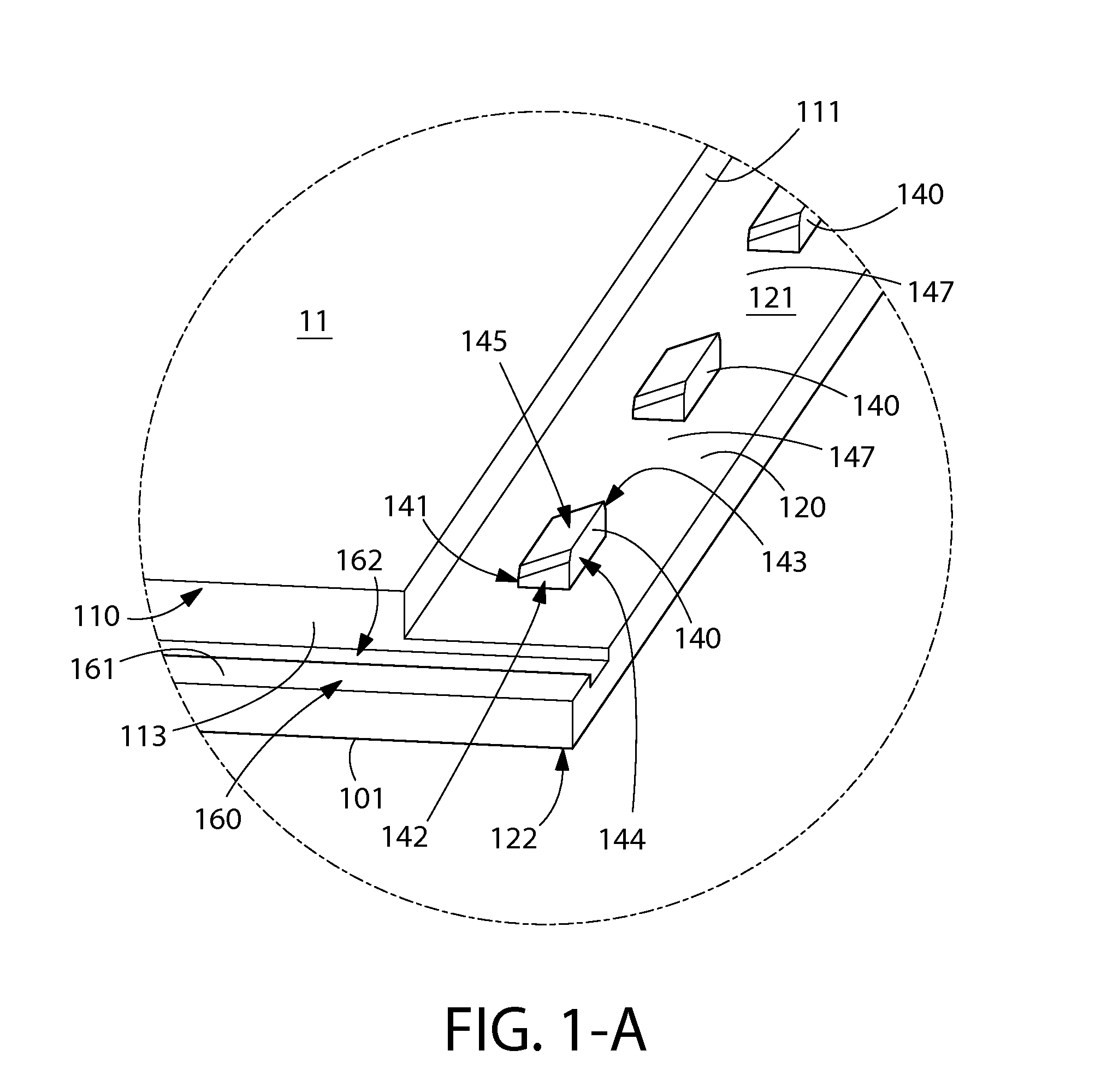
[0029]Referring first to FIGS. 1-3 concurrently, a floor panel 100 according to an embodiment of the present invention is illustrated. In one embodiment, the floor panel 100 may be a vinyl tile, h...


PUM

PropertyMeasurementUnit
length LSLaaaaaaaaaa

Abstract

A floating floor system and a floor panel and method for use with the same that includes an improved mechanical interlock system. The mechanical interlock system allows laterally adjacent floor panels that are mechanically interlocked to slide relative to one another a predetermined distance in a longitudinal direction, while prohibiting relative translation in the vertical and transverse directions. In one embodiment, the predetermined distance eliminates the need for precision cuts during installation, thereby making installation fast and easy. In a further embodiment, the invention optimizes the floor panels (and floating floor system.) to balance ease of installation and horizontal locking strength between laterally adjacent floor panels.

Description

CROSS-REFERENCE TO RELATED PATENT APPLICATIONS[0001]The present application is a U.S. National Stage Application under 35 U.S.C. §371 of PCT Application No. PCT / US2013 / 027675, filed Feb. 25, 2013, which in turn claims the benefit of U.S. Provisional Patent Application Ser. No. 61 / 613,017, filed Mar. 20, 2012, and U.S. Provisional Patent Application Ser. No. 61 / 602,389, filed Feb. 23, 2012, the entireties of which are herein incorporated by reference.FIELD OF THE INVENTION[0002]The present invention relates generally to floor systems, floor panels, and installation methods thereof, and particularly to an enhanced mechanical interlock system for said floor systems, floor panels, and installation methods thereof. The present invention is particularly suited for floating floor systems.BACKGROUND OF THE INVENTION[0003]Floating floor systems are known in the art. In existing floating floor systems, the floor panels are typically interlocked together via chemical adhesion. For example, the...

Claims


Application Information

Patent Timeline
Patent Type & Authority Patents(United States)
IPC IPC(8): E04F15/02E04F15/10
CPCE04F15/02038E04F15/105E04F15/107E04F2201/0123E04F2201/0138E04F2201/02E04F2201/021E04F2201/03E04F2203/065
Inventor RAMACHANDRA, SUNIL
Owner AFI LICENSING
Why Eureka
Try Eureka