

Articulating band saw and method
- Summary
- Abstract
- Description
- Claims
- Application Information
AI Technical Summary
Benefits of technology
Problems solved by technology
Method used
Image

Examples
example cutting
Job
[0124]Below is provided various steps in an example cutting job.
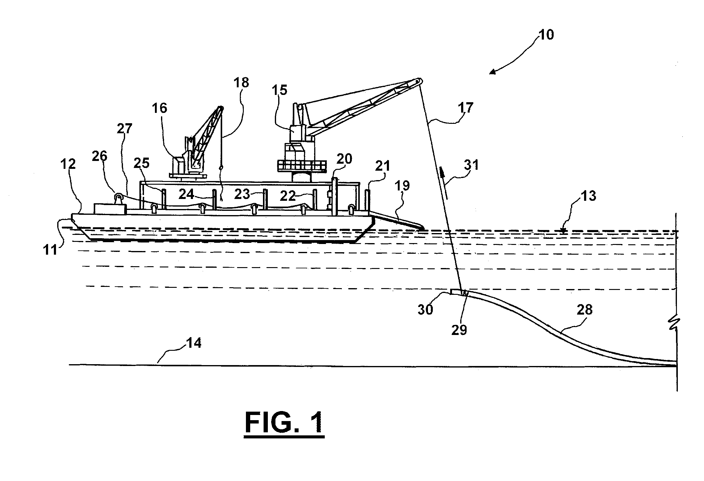
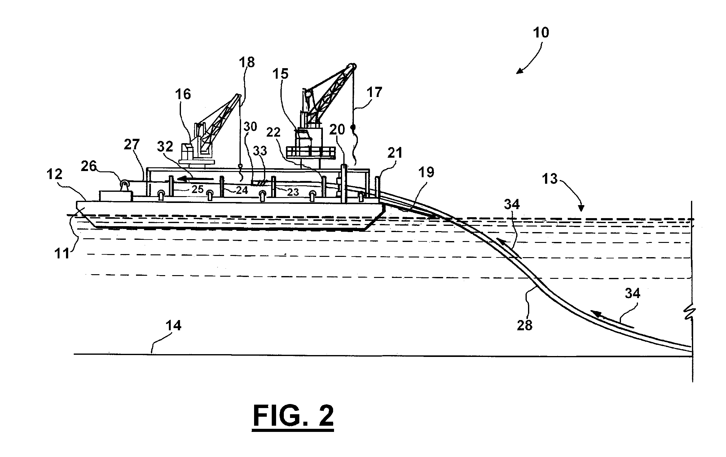
[0125]1. Job to be performed is discussed at length with Customer and associated engineers. Details including, but not limited to, tooling placement on vessel 11, shipboard power requirements, water depth, pipe sizes to be cut, offshore location, departure dock and safety orientation.
[0126]2. Articulating Band Saw 20 and support equipment can be prepared and function tested prior to transport. All items can be dispatched through a predetermined shipment carrier to the departure dock.
[0127]3. Articulating Band Saw 20 and support equipment can be transported via customer's supply vessel to the work location that could be a platform, drilling rig, drill ship, work barge 11, dive boat, or lift boat.
[0128]4. Equipment is offloaded via work platform crane 15 and placed on deck 12 in accordance with the vessel Captain or tool pusher's instructions.
[0129]5. All equipment is inspected by operator 61 personnel for transport da...
PUM
| Property | Measurement | Unit |
|---|---|---|
| Pressure | aaaaa | aaaaa |
| Pressure | aaaaa | aaaaa |
| Angle | aaaaa | aaaaa |
Abstract
Description
Claims
Application Information