However, numerous problems prevent the achievement of realistic three-dimensional object rendering on a typical user's
home computer.
However, the more polygons used to create an object, the more computations required to render the object, thus slowing down the speed at which the object is rendered.
The resolution of this problem is not easy.
Thus, the developer must assume the user's processor is slow and is therefore capable of only rendering a small number of triangles per second.
This solution, however, pleases neither the user with a low-end computer nor the user with the high-end computer.
The user with the low-end computer will most likely still have images which are slow and choppy, because the developers are unwilling to completely sacrifice realism, and the user with a high-end computer will have images which appear artificial and robotic because the application is not designed to take
advantage of the high-end
machine's greater
processing power.
In fact, on some high-end systems, the application will be too fast to play or interact with because the polygon count is too low.
Another problem facing the developer is the fact that the same object requires more detail when closer to the screen than it requires if it is in the background.
However, the most detailed version of the object cannot always be used to render the object because the application will require too much computing power to quickly and smoothly render images on the screen.
If too many polygons are used for each object, thus providing the necessary realism for the object when it is close to the screen, then the processor will not be able to achieve the above minimum
frame rate required for smooth rendering.
Typically, only three or four levels are used because storage of multiple versions of each object to be rendered can consume too much of the user'
s system resources.
First, this method has a large
impact on
system resources, as described above.
Second, when transitioning from one level to another, an effect known as object popping occurs.
The higher detailed version of an object is abruptly rendered as the object moves towards the screen, and “pops” out at the viewer, ruining the 3D immersive qualities of the application.
The
level of detail method also requires extra authoring of each version of the object, requiring more time from the developer.
Thus, the highest
level of detail cannot contain too many polygons or the image will appear slow and choppy on the low-
end user's computer.
Again, this image will also appear angular and robotic on the high-
end user's computer, as it does not take
advantage of the high-end computer's greater
processing power.


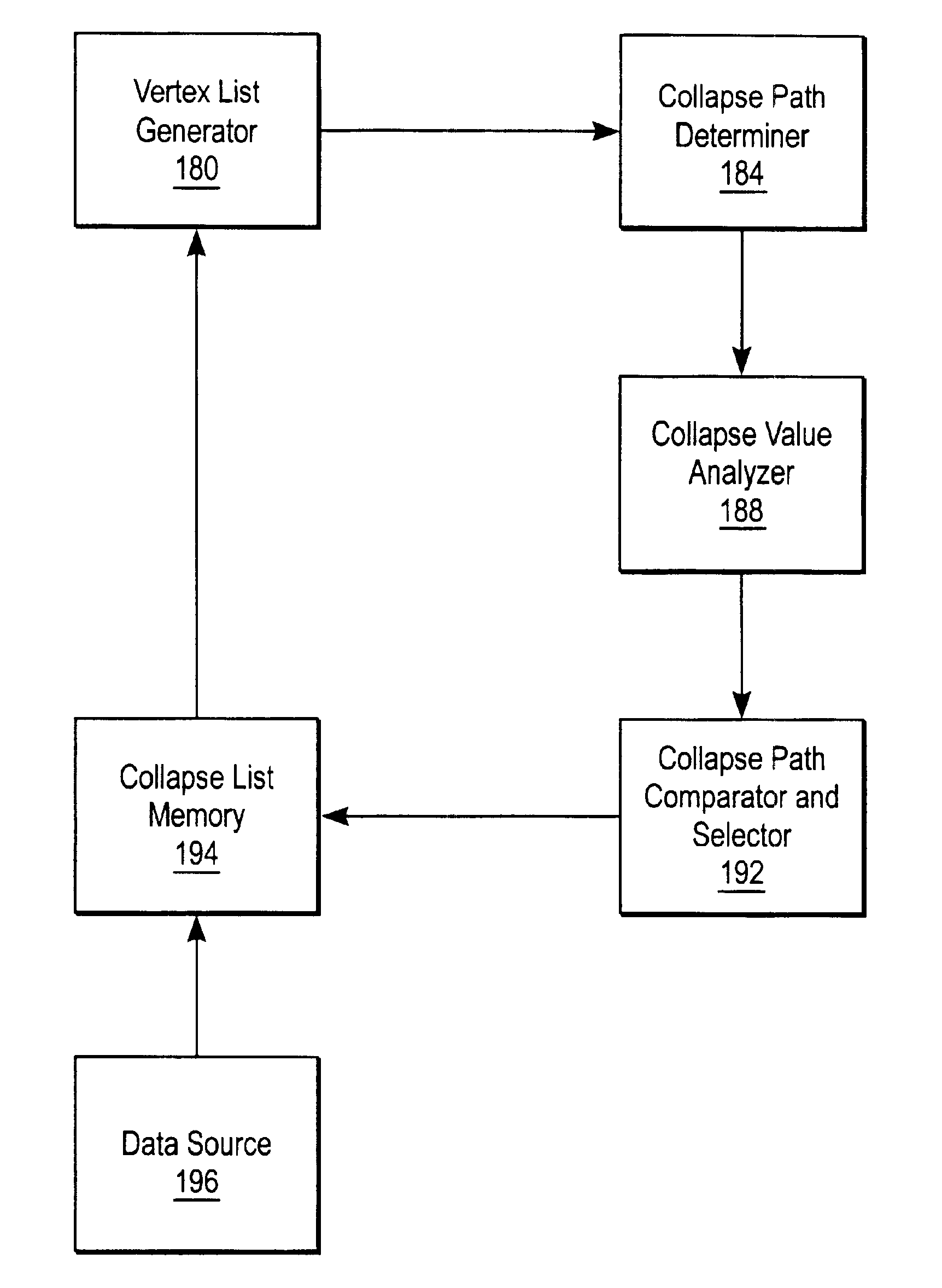
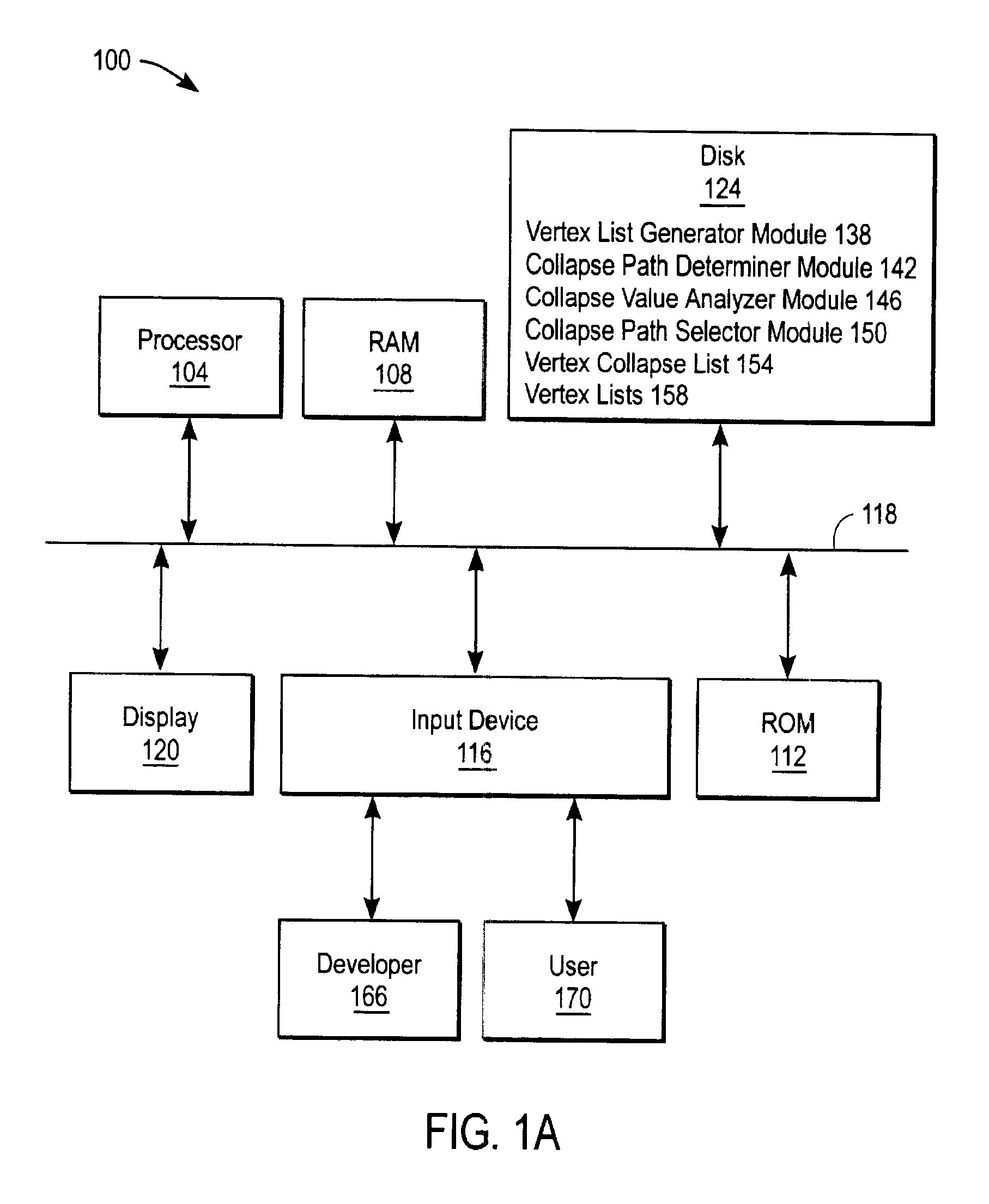
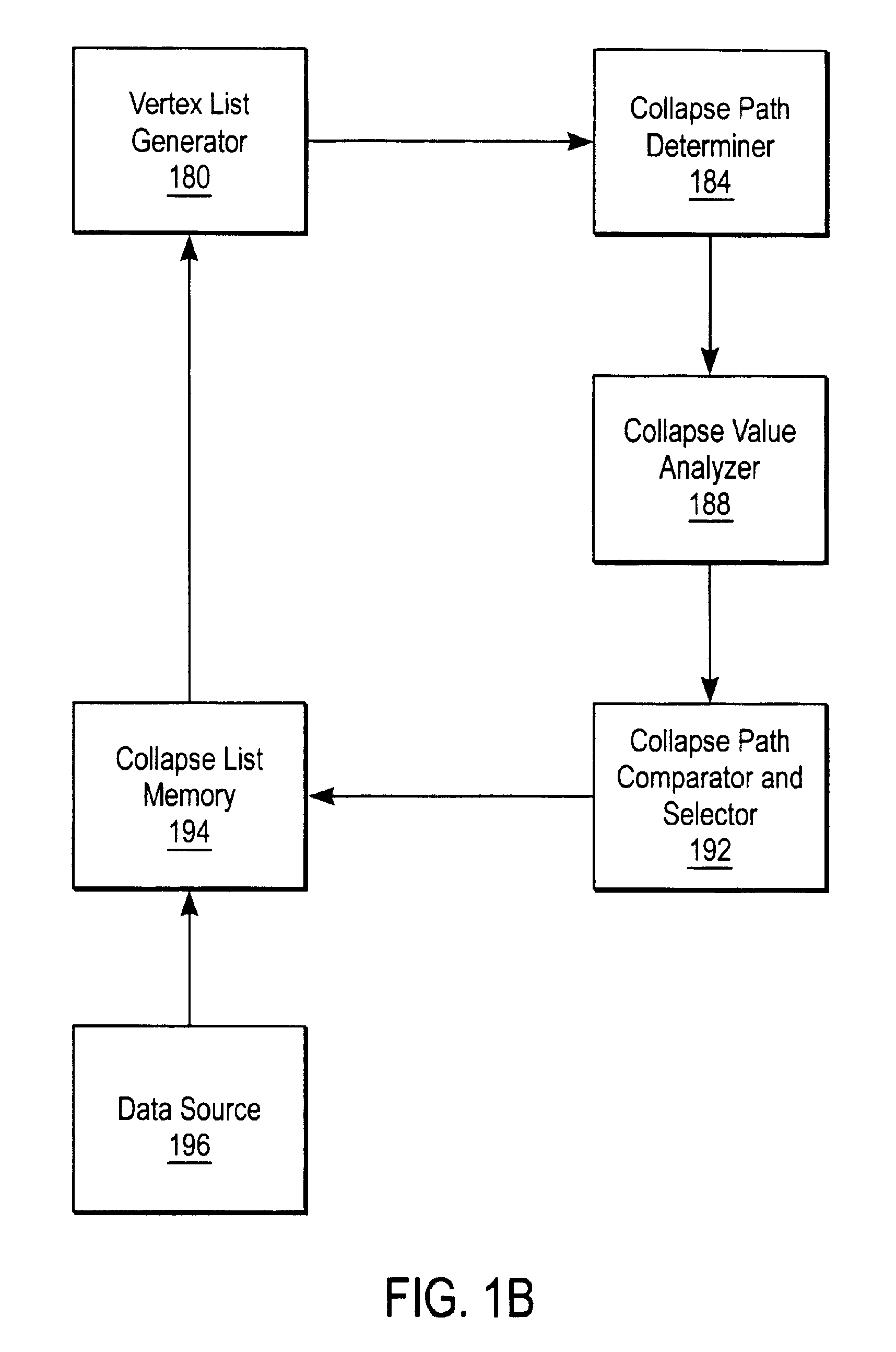