Multi channel imaging engine apparatus

Inactive Publication Date: 2005-08-23
OMNIVISION TECH INC
View PDF25 Cites 6 Cited by
  • Summary
  • Abstract
  • Description
  • Claims
  • Application Information

AI Technical Summary

Benefits of technology

[0015]An advantage of the present invention is that a relatively inexpensive video projection engine is provided for incorporation into video projection imaging devices.
[0016]A further advantage of the present invention is that sub-pixel accuracy is provided over an entire image.
[0017]Yet another advantage of the present invention is that effects of vibration are essentially eliminated, such that cooling fans can be mounted on the video projection engine wit

Problems solved by technology

However, the construction of such a device results in two or more assembly planes.
This requires complex molded parts with expensive tooling.
Since there are two or more assembly planes, the registration of the optics becomes more difficult.
This problem is made worse in an off-axis de

Method used


Image

  • Multi channel imaging engine apparatus
  • Multi channel imaging engine apparatus
  • Multi channel imaging engine apparatus

Examples


Example

[0030]The embodiments and variations of the invention described herein, and / or shown in the drawings, are presented by way of example only and are not limiting as to the scope of the invention. Unless otherwise specifically stated, individual aspects and components of the invention may be omitted or modified, or may have substituted therefore known equivalents, or as yet unknown substitutes such as may be developed in the future or such as may be found to be acceptable substitutes in the future. The invention may also be modified for a variety of applications while remaining within the spirit and scope of the claimed invention, since the range of potential applications is great, and since it is intended that the present invention be adaptable to many such variations.

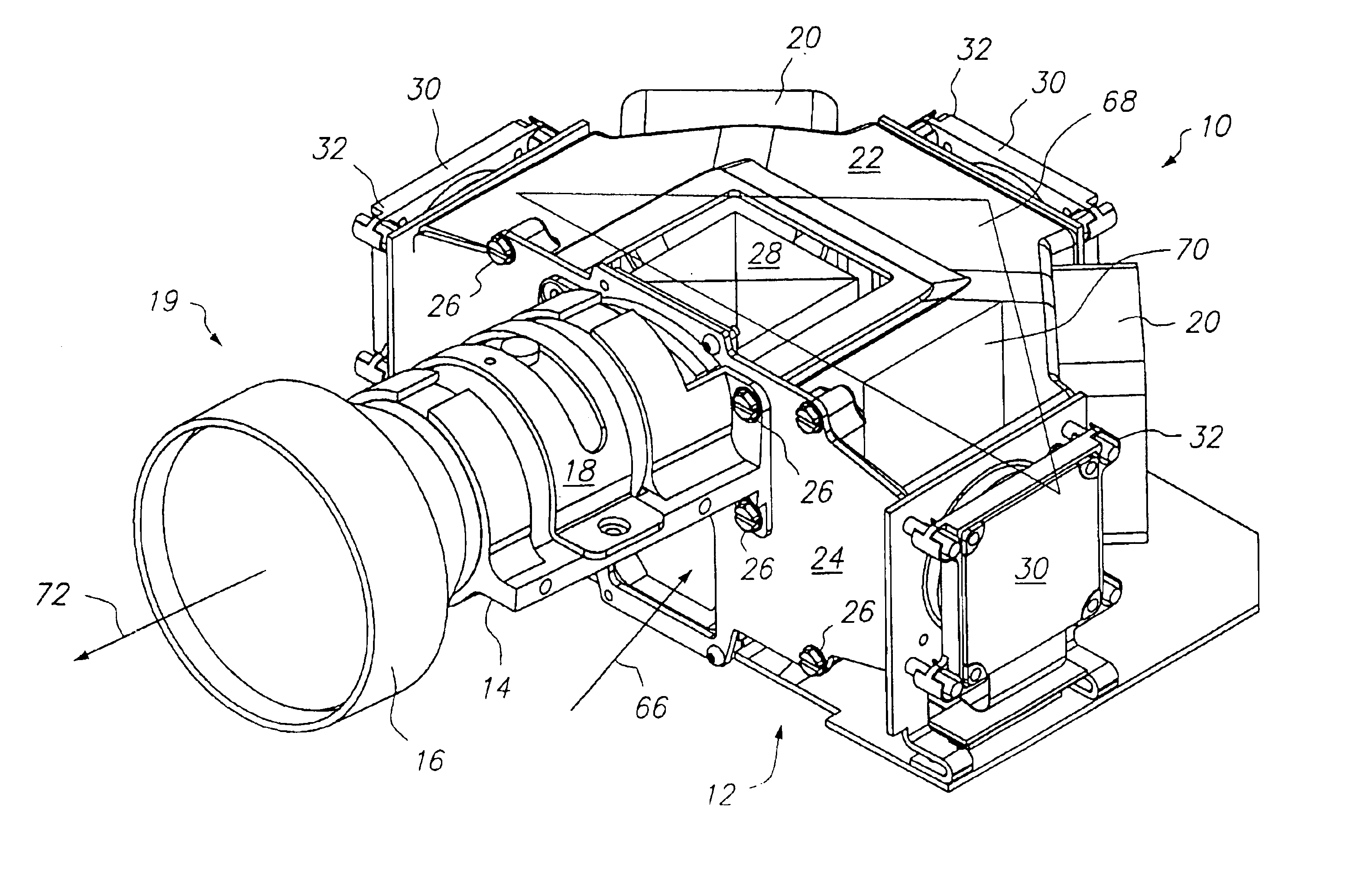
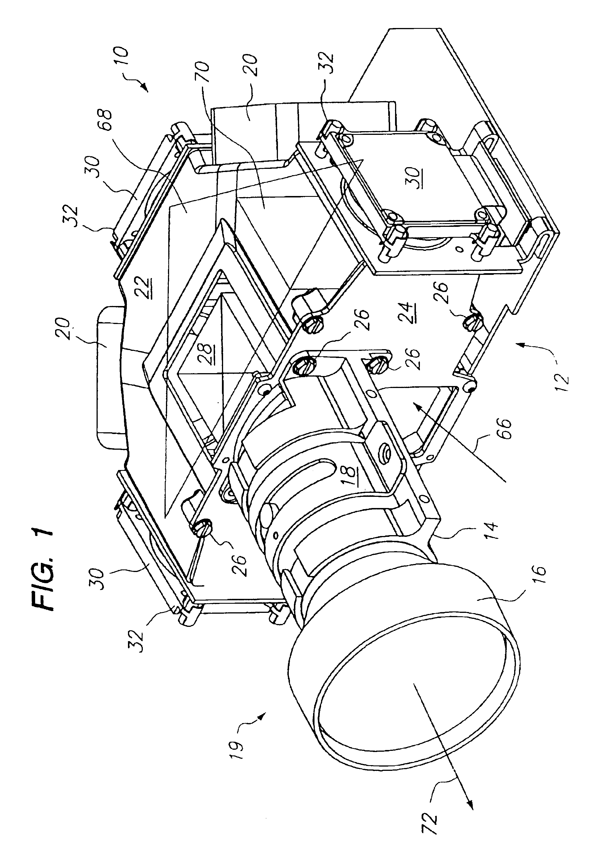
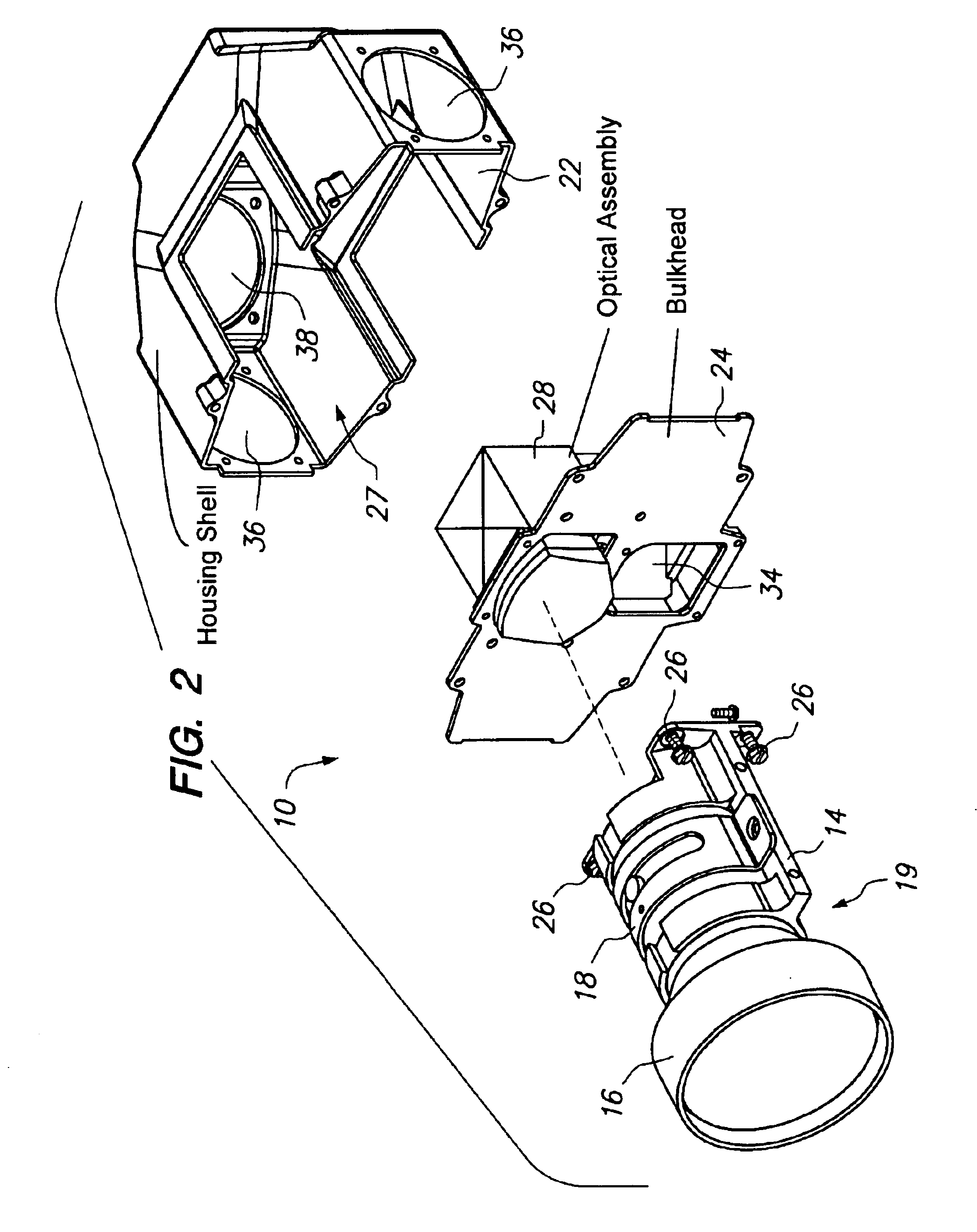
[0031]The mode for carrying out the invention, as described herein, is a multi channel imaging engine. An example of the inventive multi channel imaging engine is depicted in a perspective view in FIG. 1 and is designate...


PUM


Abstract

A multi channel video engine (10) for accepting, dividing, modifying and recombining light to project an image. A housing (12) encloses an optical assembly (28) having a dichroic mirror assembly (58) and a color cube (60). A plurality of LCD assemblies (30) accept light from the dichroic mirror assembly (58), modifies it, and reflects it to the color cube (60). A lens assembly (16) is affixed to a bulkhead (24) of the housing (12) using a lens cradle (14) and lens retainer (18). An output prism (54) aligns light onto a second plane (70) to coincide with an optical axis (72) of the lens assembly (16).

Description

RELATED APPLICATIONS[0001]This application is a continuation of U.S. Patent application Ser. No. 09 / 483,888, filed Jan. 18, 2000 now U.S. Pat. No. 6,377,318 by the same inventor, which is incorporated herein by reference in its entirety.TECHNICAL FIELD[0002]The present invention relates to the field of multi channel imaging devices, and more particularly to projection type imaging devices, wherein it is very important to accurately align physical components of the apparatus such that the color components of a resulting image will be aligned. The predominant current usage of the present inventive multi channel imaging engine is as a component of projection video display devices, wherein it is desirable to have a rugged and accurately aligned electro-optical unit for projecting well aligned color images therefrom.BACKGROUND ART[0003]The typical arrangement for multi-channel imaging systems will have a clamshell arrangement where the internal optics and components are assembled from ab...

Claims


Application Information

Patent Timeline
IPC IPC(8): H04N9/31H04N5/74
CPCH04N9/3141H04N9/3144H04N9/317H04N9/3197
Inventor MENARD, JEAN PIERRE
Owner OMNIVISION TECH INC
Why Eureka
Try Eureka