Micro light-emitting diode display panel

Active Publication Date: 2017-12-28
TCL CHINA STAR OPTOELECTRONICS TECH CO LTD
View PDF1 Cites 6 Cited by
  • Summary
  • Abstract
  • Description
  • Claims
  • Application Information

AI Technical Summary

Benefits of technology

[0018]Compared to the known techniques, the present invention provides the following advantages: the present invention provides a micro LED display panel, by disposing a plurality of active areas on the substrate arranged in an array, and a plurality of micro LEDs uniformly arranged i

Problems solved by technology

However, this approach requires a large num

Method used


Image

  • Micro light-emitting diode display panel
  • Micro light-emitting diode display panel
  • Micro light-emitting diode display panel

Examples


first embodiment

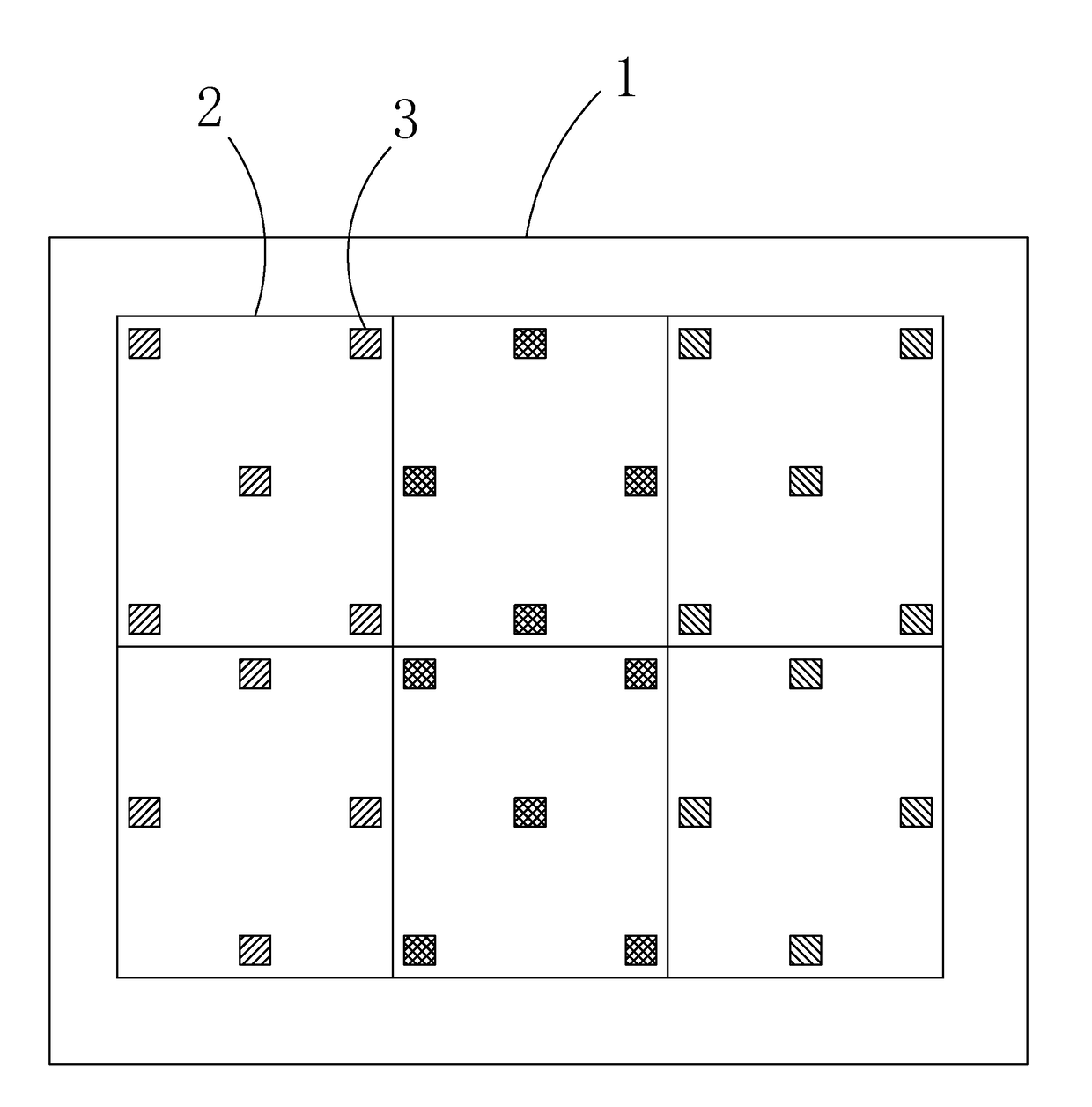
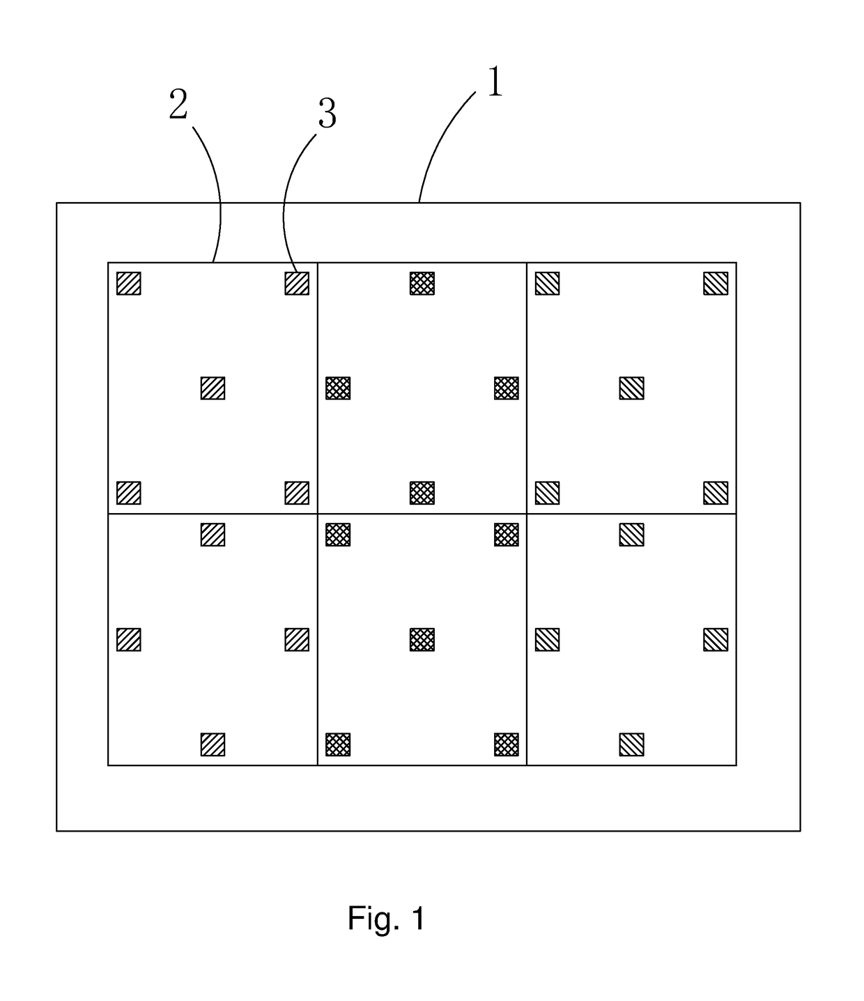
[0028]Refer to FIG. 1. In the present invention, each of the active areas 2 belonging to an odd-numbered column, odd-numbered row and the active areas 2 belonging to an even-numbered column, even-numbered row comprises five micro LEDs 3, with four micro LEDs 3 disposed at the four corners of the active area 2 and the remaining one micro LED 3 disposed at the center of the active area 2. Each of the active areas 2 belonging to an odd-numbered column, even-numbered row and the active areas 2 belonging to an even-numbered column, odd-numbered row comprises four micro LEDs 3, with four disposed respectively at the mid-point of four sides of the active area 2.

[0029]Moreover, the micro LEDs 3 in the active areas 2 of the same row have the same light color, the micro LEDs 3 in the two neighboring active areas 2 have different light colors. In the first embodiment, three colors, RGB, are used for color display, wherein for a positive integer M, the light color of the micro LEDs 3 in the act...

second embodiment

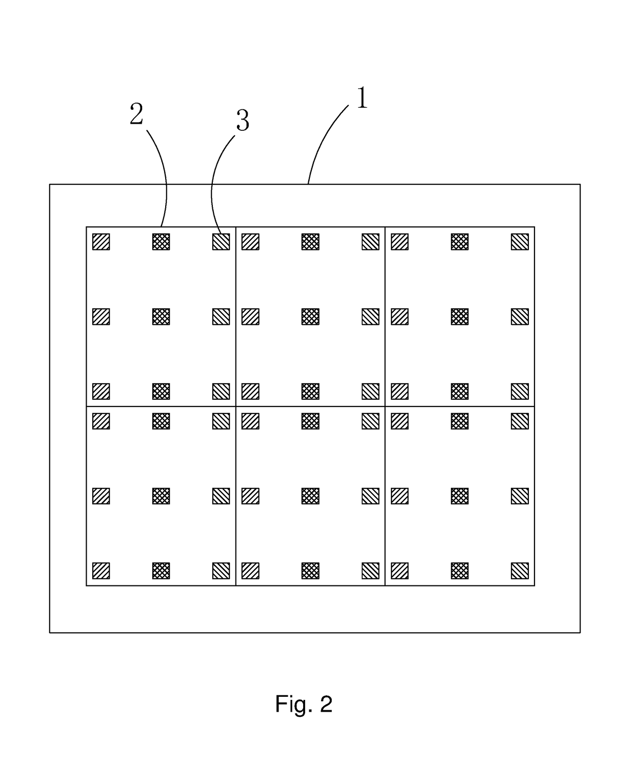
[0030]Refer to FIG. 2. In the second embodiment, each active area 2 comprises nine micro LEDs 3, arranged in an 3×3 array.

[0031]Moreover, the two neighboring micro LEDs 3 in the same active area 2 have different light colors. The light colors of the micro LEDs 3 in the three rows of the first column of each active area 2 are red, green and blue sequentially; the light colors of the micro LEDs 3 in the three rows of the second column of each active area 2 are green, red and blue sequentially; and the light colors of the micro LEDs 3 in the three rows of the third column of each active area 2 are blue, green and red sequentially.

[0032]It should be noted that light color arrangement sequence in the above embodiments is only exemplary, instead of restrictive. For example, in the first embodiment, the light color of the micro LEDs 3 in the active areas 2 of the (3M-2)-th row is green, the light color of the micro LEDs 3 in the active areas 2 of the (3M-1)-th row is red, and the light col...


PUM


Abstract

The invention provides a micro LED display panel, by disposing a plurality of active areas (2) on the substrate (1) arranged in an array, and a plurality of micro LEDs (3) uniformly arranged in each active area (2), to achieve high-resolution of micro LED display panel, and by controlling the number of micro LEDs in each active area to effectively control the production cost, while eliminating the screen door effect, to enhance market competitiveness of micro LED display panel.

Description

BACKGROUND OF THE INVENTION1. Field of the Invention[0001]The present invention relates to the field of display, and in particular to a micro light-emitting diode (micro LED, μ LED) display panel2. The Related Arts[0002]The panel display device, due to the advantages of high display quality, low power-consumption, thin size and wide application, is widely used in mobile phones, TV, PDA, digital camera, notebook PC, desktop PC, and so on, and becomes the mainstream technology.[0003]The micro LED display device is a display device which utilizes high density micro-scaled LED array integrated on a substrate as display pixels to achieve image display. Similar to a larger-scaled outdoor LED display, each pixel is addressable and individually driven to emit light, and can be viewed as a reduce-sized outdoor LED display by reducing the inter-pixel distance from cm scale to mm scale. Micro LED display device and the organic light-emitting diode (OLED) are both self-luminous, but the micro L...

Claims


Application Information

Patent Timeline
IPC IPC(8): H01L27/32H01L33/20
CPCH01L27/326H01L33/20H01L27/3206G09F9/302G09F9/33G09G3/32H01L25/0753G09G3/3208H10K59/121H10K59/30H01L25/075H01L27/153H01L27/156
Inventor CHEN, LIXUAN
Owner TCL CHINA STAR OPTOELECTRONICS TECH CO LTD
Why Eureka
Try Eureka