

Apparatus and method for recovering effective resources including nitrogen and phosphorus
Active Publication Date: 2021-11-18
BKT
View PDF0 Cites 0 Cited by
- Summary
- Abstract
- Description
- Claims
- Application Information
AI Technical Summary
Benefits of technology
The present invention allows for the efficient recovery of various resources, such as methane gas, nitrogen, and phosphorus, while minimizing the use of chemicals. Additionally, it allows for the effective recovery of nitrogen and phosphorus from organic waste by appropriate pretreatment and the use of by-products.
Problems solved by technology
Most of the digestate generated through anaerobic digestion is transferred to a sewage treatment facility and processed but, because of containing high concentrations of nitrogen and phosphorus, puts a burden on the water treatment process.
To address this problem, a purification facility removes nitrogen and phosphorus by performing a purification treatment so as to partially mitigate the burden on the water treatment process, but a large amount of money is required for the construction and maintenance for the facility.
However, since a large amount of strong acid solution needs to be consumed due to the high alkalinity of the digestion waste of livestock manure, the elution of phosphorus costs a lot.
However, in the United States, a large amount of cow manure may be produced because scraping-type barns are used.
It is known that when nitrogen and phosphorus are continuously injected into farmland for a long period of time, unused nitrogen may move to the ground and contaminate groundwater, or phosphorus adsorbed in the soil may flow out along with rainwater, polluting rivers and lakes.
Although nitrogen may be mostly recovered by a denitrification process, phosphorus is not easy to recover.
For this reason, since the solids in organic waste, along with a significant amount of phosphorus, are removed during a purification process, it is quite difficult to recover phosphorus by the conventional methods.
Method used
View moreImage
Smart ImageViewing Examples

Examples
first embodiment
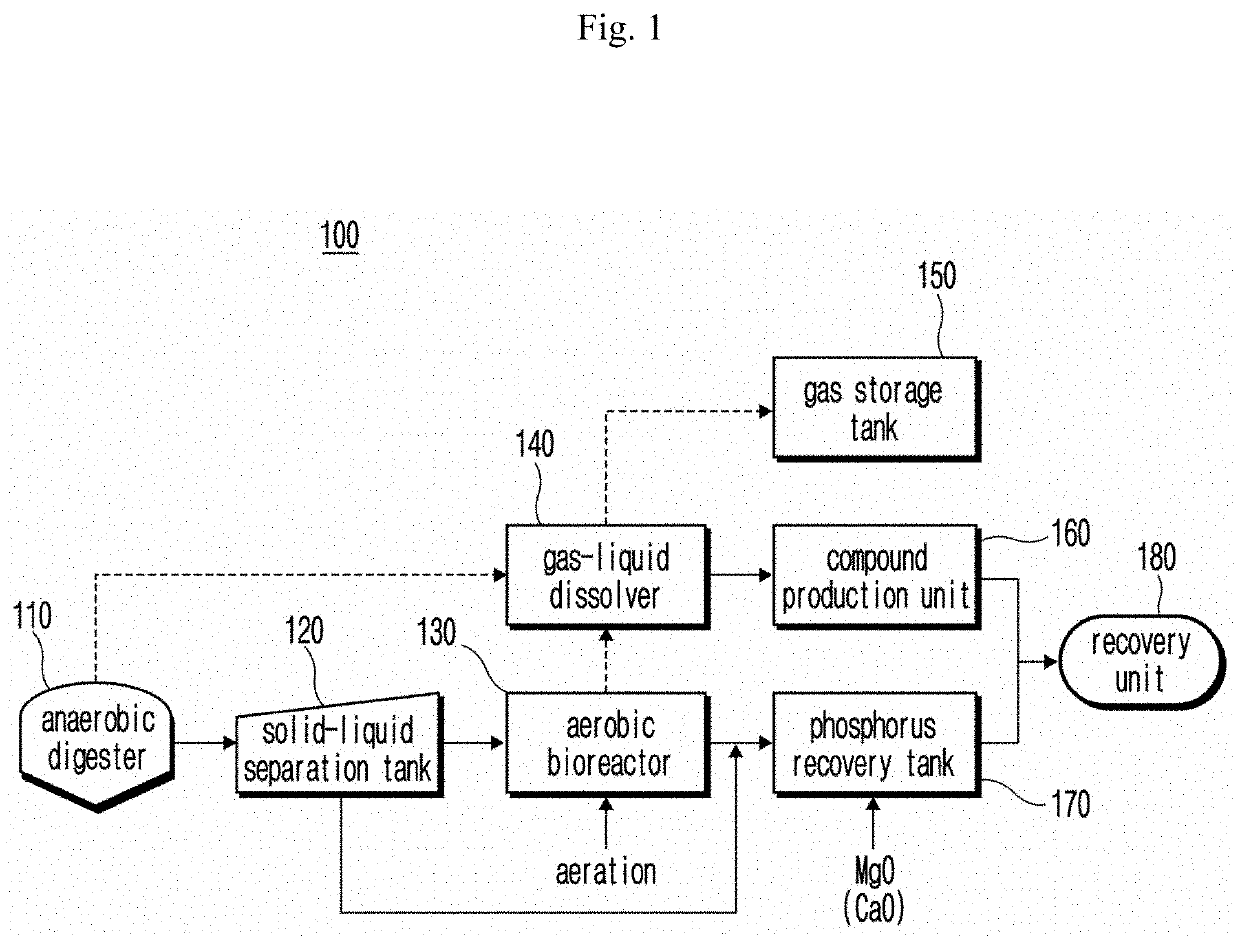
[0024]FIG. 1 is a view illustrating a configuration of an effective resource recovery device according to the present invention.
second embodiment
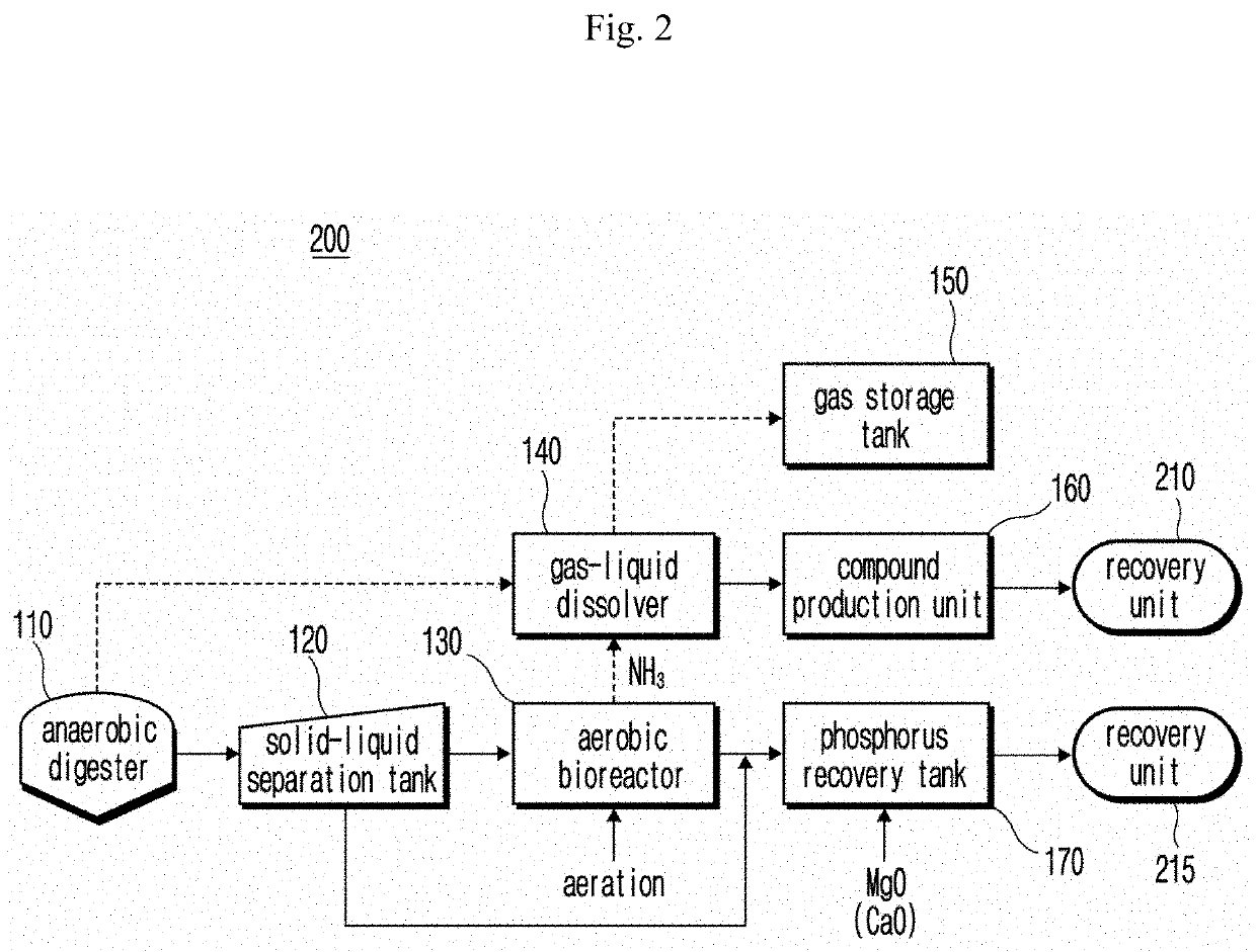
[0025]FIG. 2 is a view illustrating a configuration of an effective resource recovery device according to the present invention.
third embodiment
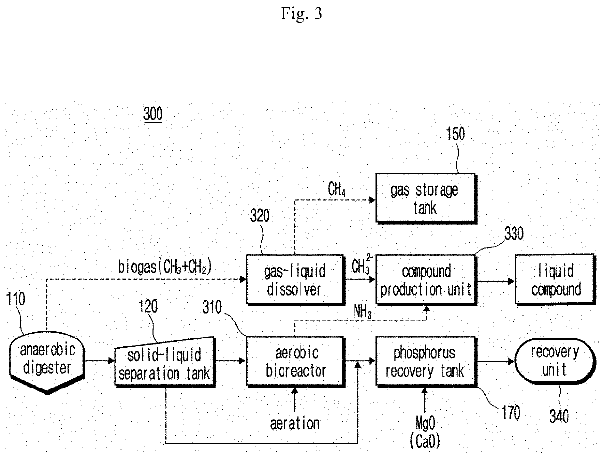
[0026]FIG. 3 is a view illustrating a configuration of an effective resource recovery device according to the present invention.
Login to View More PUM
| Property | Measurement | Unit |
|---|---|---|
| Temperature | aaaaa | aaaaa |
| Solubility (mass) | aaaaa | aaaaa |
Abstract
Disclosed are an apparatus and a method for recovering effective resources including nitrogen and phosphorus. According to one aspect of the present embodiment, provided are an apparatus and a method for recovering effective resources, which efficiently recover resources such as methane, nitrogen, and phosphorus while minimizing the use of chemicals.
Description
TECHNICAL FIELD[0001]The present invention relates to a device and method for recovering effective resources including nitrogen and phosphorus for organic waste.BACKGROUND ART[0002]The description of the Discussion of Related Art section merely provides information that may be relevant to embodiments of the disclosure but should not be appreciated as necessarily constituting the prior art.[0003]Anaerobic digestion technology is a representative technology for reducing organic waste, such as livestock manure, food waste or sewage waste and is applied to public livestock manure treatment facilities, food recycling facilities, or sewage treatment facilities. Anaerobic digestion technology not only reduces organic waste but also recovers biogas containing 60% methane content and 40% carbon dioxide as by-products. Most of the digestate generated through anaerobic digestion is transferred to a sewage treatment facility and processed but, because of containing high concentrations of nitrog...
Claims
Login to View More Application Information
Patent Timeline
 IPC IPC(8): B01D47/02C02F9/00
CPCB01D47/02C02F1/20C02F9/00C12P3/00C02F11/121C02F1/5254C02F11/04C02F3/1215C02F3/307C02F2101/16C02F2103/20C05F17/15C05F17/50Y02W10/10C02F3/308C02F2101/105
InventorRHU, DAEHWANCHOI, JAEMINJUNG, MINKIHWANG, HOJAEKIM, SEYEONGTASAKI, KEN
OwnerBKT