Method and system for aligning a point of aim with a point of impact for a projectile device

a projectile device and point of impact technology, applied in the field of firearms, can solve the problems of difficult to determine the distance to turn the adjustment dial, difficult to hear in certain environments, and the knobs of the scope adjustment can often create audible clicks as they are turned

Active Publication Date: 2015-12-03
UMAREX USA
View PDF0 Cites 26 Cited by
  • Summary
  • Abstract
  • Description
  • Claims
  • Application Information

AI Technical Summary

Problems solved by technology

Unfortunately, it is often difficult to determine how far to turn the adjustment dials because the manufacturers guidelines may be based on a distance different from the desired zeroing distance.
Furthermore, the scope adjustment knobs often create audible clicks as they are turned.
These clicks need to be counted, but they may be hard to hear in certain environments, especially if hearing protection is being worn (as is often the case around certain firearms).
To make matters worse, the springs inside many of the scope adjustment knobs often relax over time, resulting in inaccurate offset compensation even if a desired number of clicks or adjustment turns is used.
The process is also further complicated and delayed if the scope adjustments are more rudimentary and / or if the projectile device operator is not highly skilled.
Such zeroing techniques can be very wasteful of ammunition or other projectiles.
The scope, or other aiming device, however, cannot be aligned with the laser light since the light travels in a straight line as opposed to the curved trajectory of a bullet.
This increases the opportunity for human error.
Such errors can be complicated by wobble from the magnetically attached laser arbor.
Furthermore, some firearms can't be used with a magnetic laser arbor because the barrels are not iron-based and therefore non-magnetic.
On top of this, the more serious firearm enthusiasts will not use such a device which intrudes into the barrel crown because it may cause distortion to the barrel's grooving.
While crown insertion is avoided, the linear trajectory of the laser results in similar downfalls to the previously described solution.
Furthermore, the spot radius of existing cartridge lasers is quite large, making it further difficult to zero the point of aim onto a point of impact.
Furthermore, as yet another magnetic method, such a technique does not work with firearms made from non-iron-based materials.

Method used


Image

  • Method and system for aligning a point of aim with a point of impact for a projectile device
  • Method and system for aligning a point of aim with a point of impact for a projectile device
  • Method and system for aligning a point of aim with a point of impact for a projectile device

Examples


Embodiment Construction

[0218]The term “about” is used herein to mean approximately, roughly, around, or in the region of. When the term “about” is used in conjunction with a numerical range, it modifies that range by extending the boundaries above and below the numerical values set forth. In general, the term “about” is used herein to modify a numerical value above and below the stated value by a variance of 20 percent up or down (higher or lower).

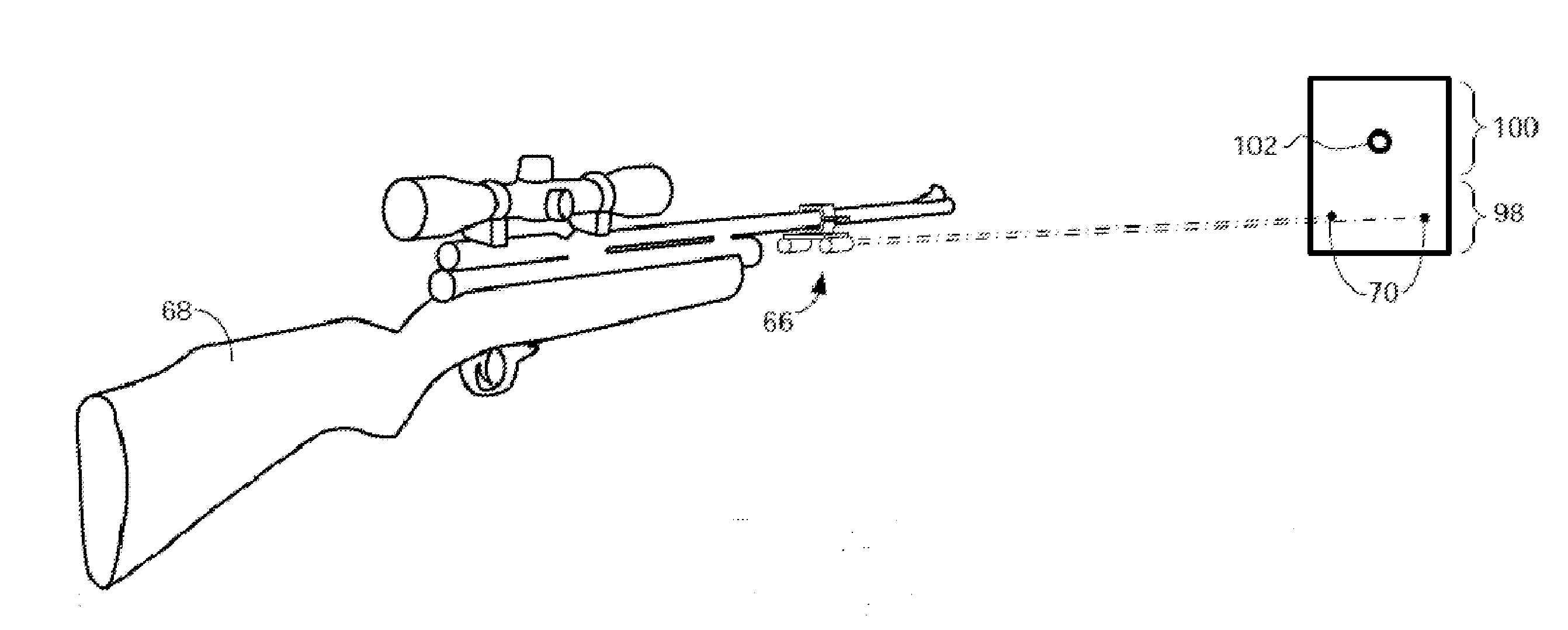
[0219]The term “marking beam” or “beam” is used herein to mean (1) a beam emanating from a superposition device, the beam is used in producing a dot in a first target area where the dot is to be marked as a reference point in a first target area, or (2) a beam emanating from a superposition device, the beam is used in superimposing a reference point that is pre-printed or otherwise made available in a first target area.

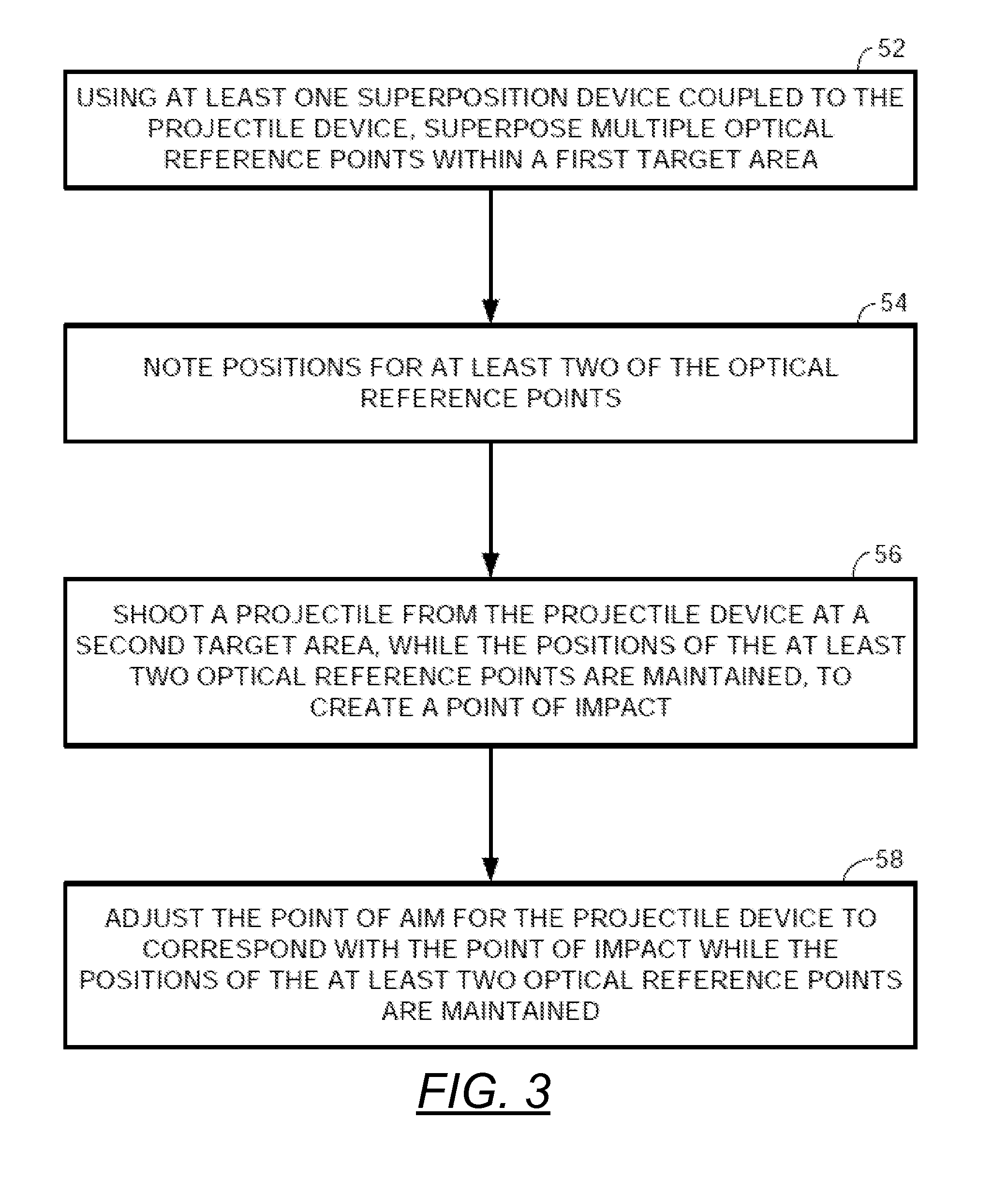
[0220]FIG. 3 illustrates one embodiment of a method of aligning a point of aim with a point of impact for a projectile device. A projectile devic...


PUM


Abstract

A method of aligning a point of aim with a point of impact for a projectile device is disclosed. Using a superposition device coupled to the projectile device, at least one reference point is superposed within a first target area with at least one beam of the superposition device. A position for at least one of the reference points is noted. A projectile is shot from the projectile device at a second target area, while the position of the at least one reference point is maintained, to create the point of impact. The point of aim for the projectile device is adjusted to correspond with the point of impact while the position of the at least one reference points is maintained.

Description

PRIORITY CLAIM AND RELATED APPLICATIONS[0001]This continuation-in-part application claims the benefit of priority from non-provisional application U.S. Ser. No. 14 / 288,872 filed May 28, 2014. Said application is incorporated by reference in its entirety.BACKGROUND OF THE INVENTION[0002]1. The Field of the Invention[0003]The claimed invention generally relates to firearms and other projectile devices. More particularly, the claimed invention relates to methods and systems for aligning a point of aim with a point of impact for a projectile device. The claimed invention also relates to methods and systems for indicating a relationship between a point of aim and a point of impact for a projectile device.[0004]2. Background Art[0005]Firearms, and other projectile devices such as air guns, pellet guns, and bows, are often provided with an aiming device such as, but not limited to a scope, an iron sight, a dot sight, a holographic sight, a shotgun sight, a bead sight, or a ramp sight.[0006...

Claims


Application Information

Patent Timeline
Patent Type & Authority Applications(United States)
IPC IPC(8): F41G3/00
CPCF41G3/005F41G1/35F41J2/00F41G1/38F41G3/323F41G1/545F41G1/54F41G1/345
Inventor HANCOSKY, JACK
Owner UMAREX USA
Why Eureka
Try Eureka