System and method for using digital displays without optical correction devices

a technology of optical correction device and display screen, which is applied in the field of system and method of using digital displays without optical correction device, can solve the problem of making it much more difficult for unauthorized users to view information presented on display screen

Inactive Publication Date: 2015-12-10
MOALEM MEHRAN
View PDF6 Cites 9 Cited by
  • Summary
  • Abstract
  • Description
  • Claims
  • Application Information

AI Technical Summary

Benefits of technology

The invention improves computers by allowing people to use regular displays instead of wearing head mounts. This makes it more comfortable for them and allows for better performance.

Problems solved by technology

The technical problem addressed in this patent is how to improve computer display screens to better meet the needs of people who suffer from common vision issues such as nearsightedness or farsightedness. Current solutions require wearing special corrective devices when using these types of computers, but an improvement could make it easier for everyone to enjoy them without having to struggle through their limitations.

Method used


Image

  • System and method for using digital displays without optical correction devices
  • System and method for using digital displays without optical correction devices
  • System and method for using digital displays without optical correction devices

Examples


Embodiment Construction

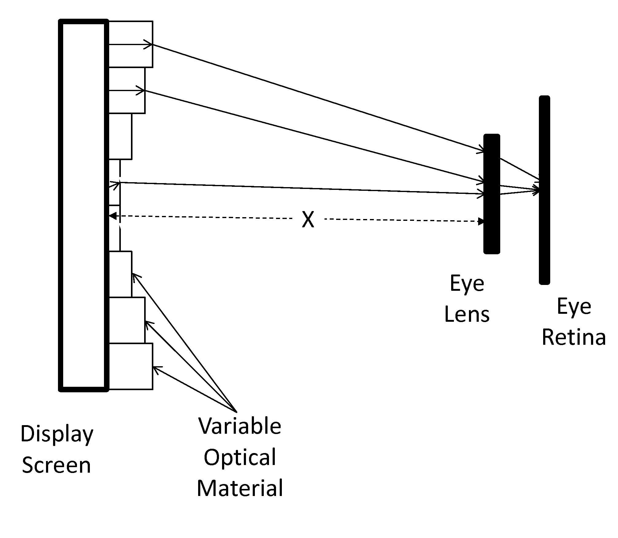
[0013]Digital devices have screen cells referred to as pixels that are turned on and off in combination to project an image or text on the screen. The higher the number of pixels the higher the digital resolution of the screen and the higher number of colors in each pixel the higher the color resolution of the screen will be. The state of each pixel is determined by processing chips used in the digital device. Examples of such processors are the special chips in the graphics board of a personal computer or display chips in its motherboard. The objective without the benefit of current invention is for the combined output of the screen pixels appearing as a sharp image viewable without eye strain to the user at a certain distance (typically 30 cm) from the front of the screen.

[0014]We use the same or similar hardware but enhance the capability by adding a software solution to defocus the image just enough that it becomes sharp and crisp for an eye which is impaired. For example eyes w...


PUM


Abstract

A computer implemented system and method to produce display screen images intended to be seen clearly by users with various eye problems such as myopia and astigmatism. Here the system receives input regarding the desired optical correction needed to allow the user to see the image clearly, such as by determining the distance to the user and also optionally calibrating the system according to the degree of optical correction needed by the user. In some embodiments, the display screen may have a plurality of pixel addressed light deflectors configured to change the angle of light emitted by the display screen at various locations in order to bring the computer generated image in better focus. In other embodiments, the system may convolute the display images in order to compensate for eye abnormalities such as astigmatism. In other embodiments, both light deflectors and image convolution methods may be used.

Description


Claims


Application Information

Patent Timeline
Owner MOALEM MEHRAN
Why Eureka
Try Eureka