Torsional vibration damper for hydrokinetic torque coupling device

Active Publication Date: 2015-12-17
VALEO EMBRAYAGES SAS
View PDF5 Cites 52 Cited by
  • Summary
  • Abstract
  • Description
  • Claims
  • Application Information

AI Technical Summary

Benefits of technology

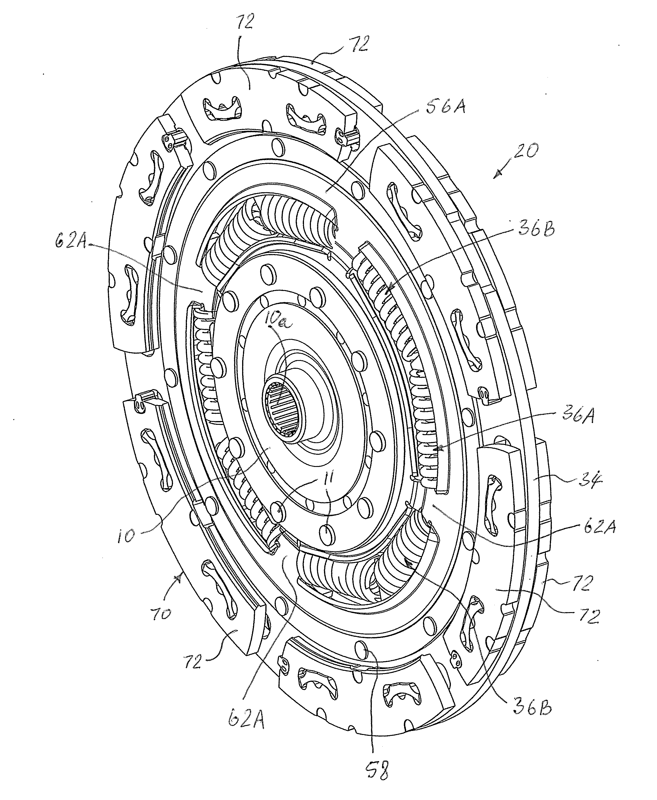
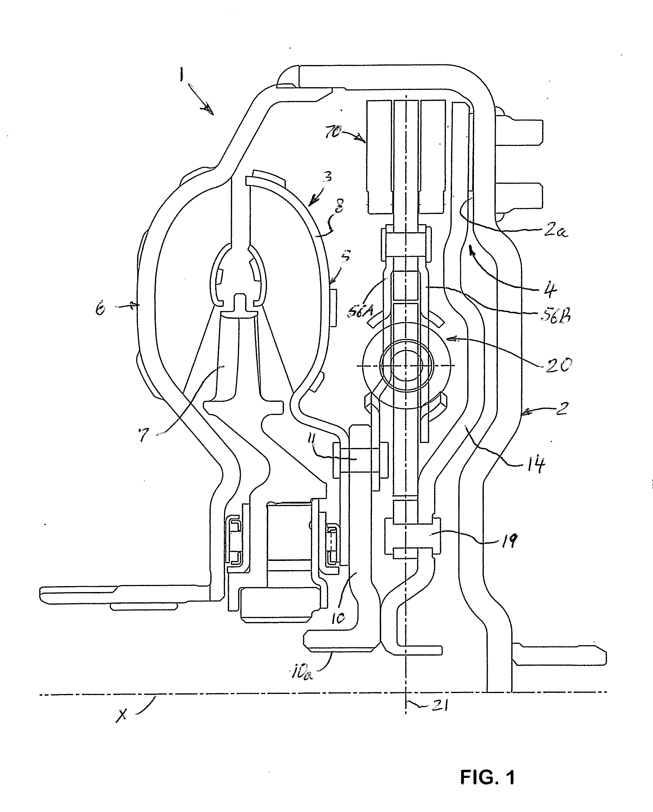
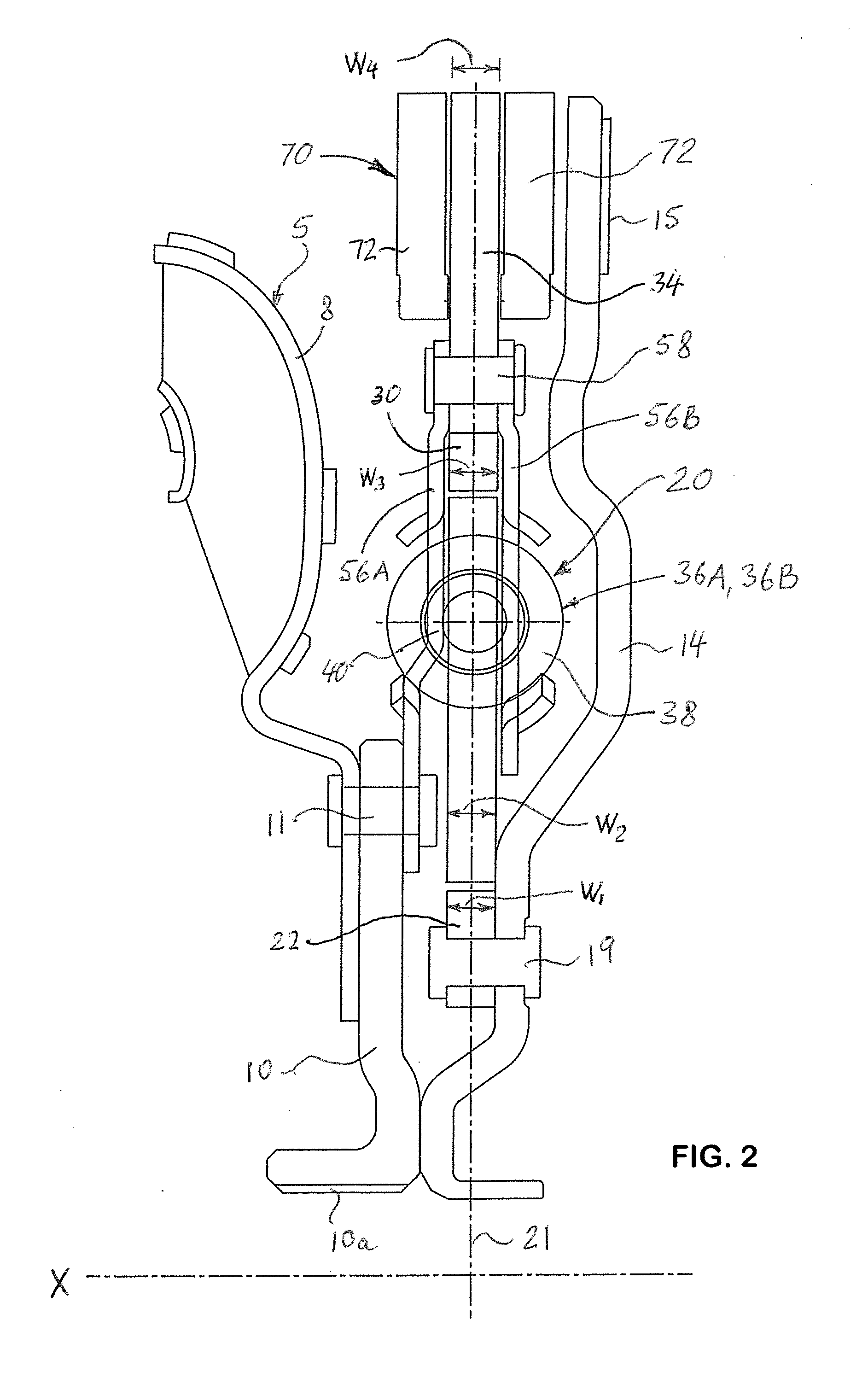
[0009]According to a first aspect of the invention, there is provided a torsional vibration damper for a hydrokinetic torque coupling device. The torsional vibration damper of the present invention comprises a driven plate rotatable about a rotation axis, an intermediate plate rotatably mounted about the driven plate coaxially with the rotation axis, a back plate rotatably mounted about the intermediate plate coaxially with the rotation axis, a plurality of circumferentially acting elastic members interposed between the driven plate and the intermediate plate, and a damper retainer plate non-moveably secured to the back plate coaxially with the rotation axis. The damper retainer plate is operatively connected to the elastic members. The driven plate, the intermediate plate and the back plate are aligned with each other along a radial axis perpendicular to the rotation axis.
[0010]According to a second aspect of the present invention, there is provided a hydrokinetic torque coupling device for coupling together a driving shaft and a driven shaft. The hydrokinetic torque coupling device comprises a casing rotatable about a rotation axis, a torque converter including an impeller wheel and a turbine wheel disposed in the casing coaxially with the rotation axis, a turbine hub, a lock-up clutch including a locking piston axially moveable along the rotation axis to and from a substantially radial locking wall of the casing so as to selectively engage the locking piston against the locking wall of the casing, and a torsional vibration damper. The torsional vibration damper comprises a drive plate rotatable about the rotation axis and fixed to the locking piston, a driven plate non-rotatably coupled to the drive plate and mounted about the drive plate coaxially with the rotation axis, an intermediat

Problems solved by technology

An internal combustion engine exhibits irregularities due to the succession of combustion events in the engine cylinders.
T

Method used


Image

  • Torsional vibration damper for hydrokinetic torque coupling device
  • Torsional vibration damper for hydrokinetic torque coupling device
  • Torsional vibration damper for hydrokinetic torque coupling device

Examples


Embodiment Construction

[0026]Reference will now be made in detail to exemplary embodiments and methods of the invention as illustrated in the accompanying drawings, in which like reference characters designate like or corresponding parts throughout the drawings. It should be noted, however, that the invention in its broader aspects is not limited to the specific details, representative devices and methods, and illustrative examples shown and described in connection with the exemplary embodiments and methods.

[0027]This description of exemplary embodiments is intended to be read in connection with the accompanying drawings, which are to be considered part of the entire written description. In the description, relative terms such as “horizontal,”“vertical,”“up,”“down,”“upper”, “lower”, “right”, “left”, “top” and “bottom” as well as derivatives thereof (e.g., “horizontally,”“downwardly,”“upwardly,” etc.) should be construed to refer to the orientation as then described or as shown in the drawing figure under ...


PUM


Abstract

A torsional vibration damper of a hydrokinetic torque coupling device, comprises a driven plate rotatable about a rotation axis, an intermediate plate rotatably mounted about the driven plate coaxially with the rotation axis, a back plate rotatably mounted about the intermediate plate coaxially with the rotation axis, a plurality of circumferentially acting elastic members interposed between the driven plate and the intermediate plate, and a damper retainer plate non-moveably secured to the back plate coaxially with the rotation axis. The damper retainer plate is operatively connected to the elastic members. The driven plate, the intermediate plate and the back plate are aligned with each other along a radial axis perpendicular to said rotation axis.

Description

BACKGROUND OF THE INVENTION[0001]1. Field of the Invention[0002]The present invention generally relates to hydrokinetic torque coupling devices, and more particularly to a hydrokinetic torque coupling device with a torsional vibration damper.[0003]2. Description of the Prior Art[0004]An internal combustion engine exhibits irregularities due to the succession of combustion events in the engine cylinders. Torsion damping devices allow these irregularities to be filtered before the drive torque is transmitted to an automotive transmission. This is because the vibrations must be damped before they enter the transmission and produce unacceptably troublesome noise. To accomplish this, it is known to interpose a torsion damping device between a drive shaft and a transmission (or driven) shaft. The torsion damping device is generally arranged in a hydrokinetic torque coupling device that allows temporary rotational connection of the drive shaft to the transmission shaft.[0005]Typically, a h...

Claims


Application Information

Patent Timeline
IPC IPC(8): F16F15/134F16H45/02
CPCF16F15/1343F16H2045/0221F16H45/02F16F15/13492F16F15/145F16H2045/0205F16H2045/0263
Inventor LEE, SUNGCHULARHAB, RABAH
Owner VALEO EMBRAYAGES SAS
Why Eureka
Try Eureka