Smart lock systems and methods

a smart lock and lock technology, applied in the field of electronic door locks, can solve the problem that the power transmitter cannot transmit electricity to the power receiver, and achieve the effect of reducing the cost of operation and maintenan

Active Publication Date: 2015-12-24
SKYBELL TECH IP LLC
View PDF4 Cites 34 Cited by
  • Summary
  • Abstract
  • Description
  • Claims
  • Application Information

AI Technical Summary

Benefits of technology

[0029]The strike plate can be configured to be coupled to the door frame. The power transmitter can be configured to receive the electricity from the transformer. The power receiver can be electrically coupled to the electrical control system such that the power receiver is configured to provide the electricity to the electrical control system such that the electrical control system is capable of operating the bolt. The electrical control system can govern the position of a solenoid that is mechanically coupled to the bolt such that the solenoid can move the bolt to locked and unlocked positions.

Problems solved by technology

If the power transmitter is not placed within sufficient proximity relative to the power receiver, then the power transmitter is not capable of transmitting the electricity to the power receiver.

Method used


Image

  • Smart lock systems and methods
  • Smart lock systems and methods
  • Smart lock systems and methods

Examples


lock history embodiments

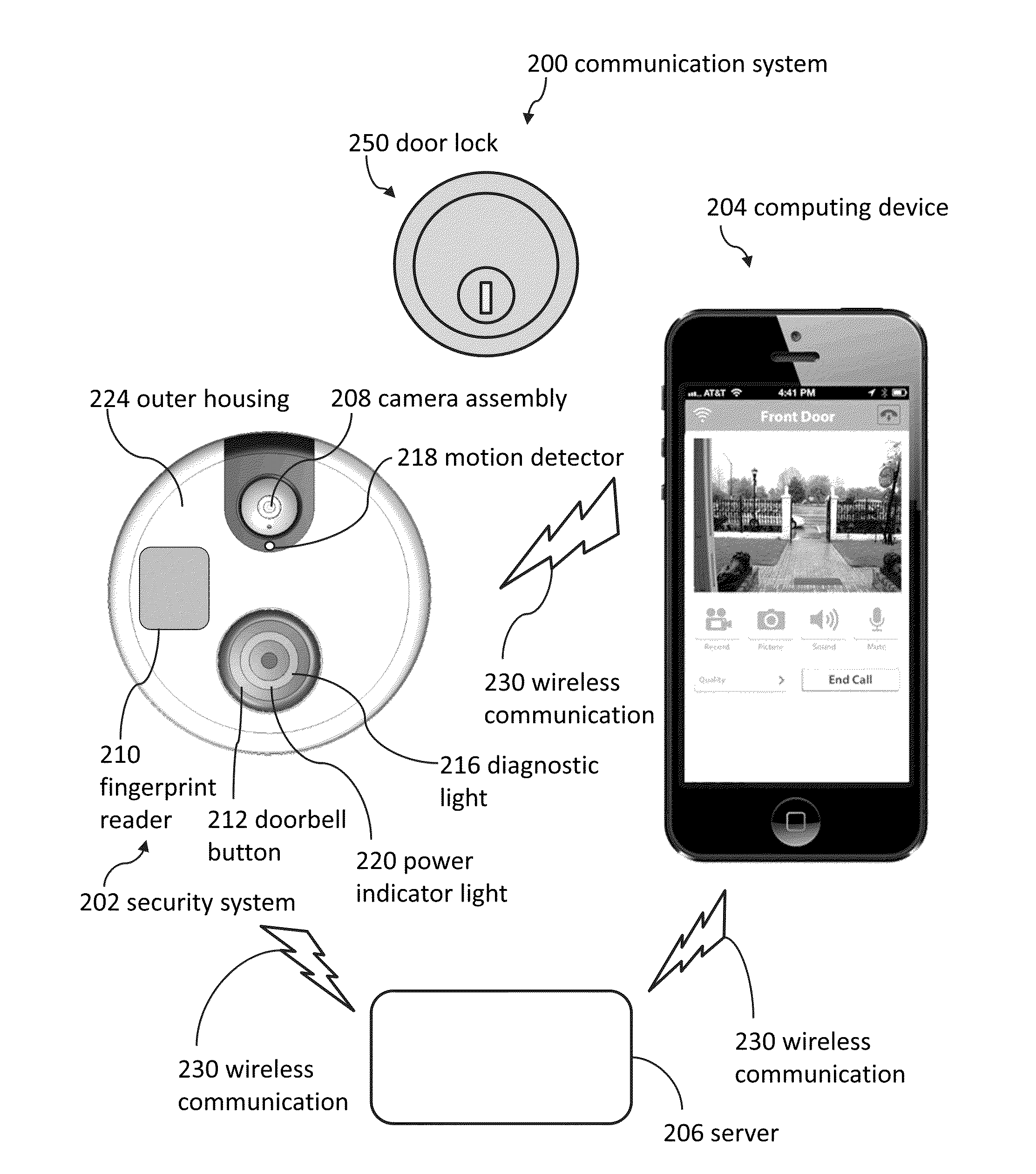
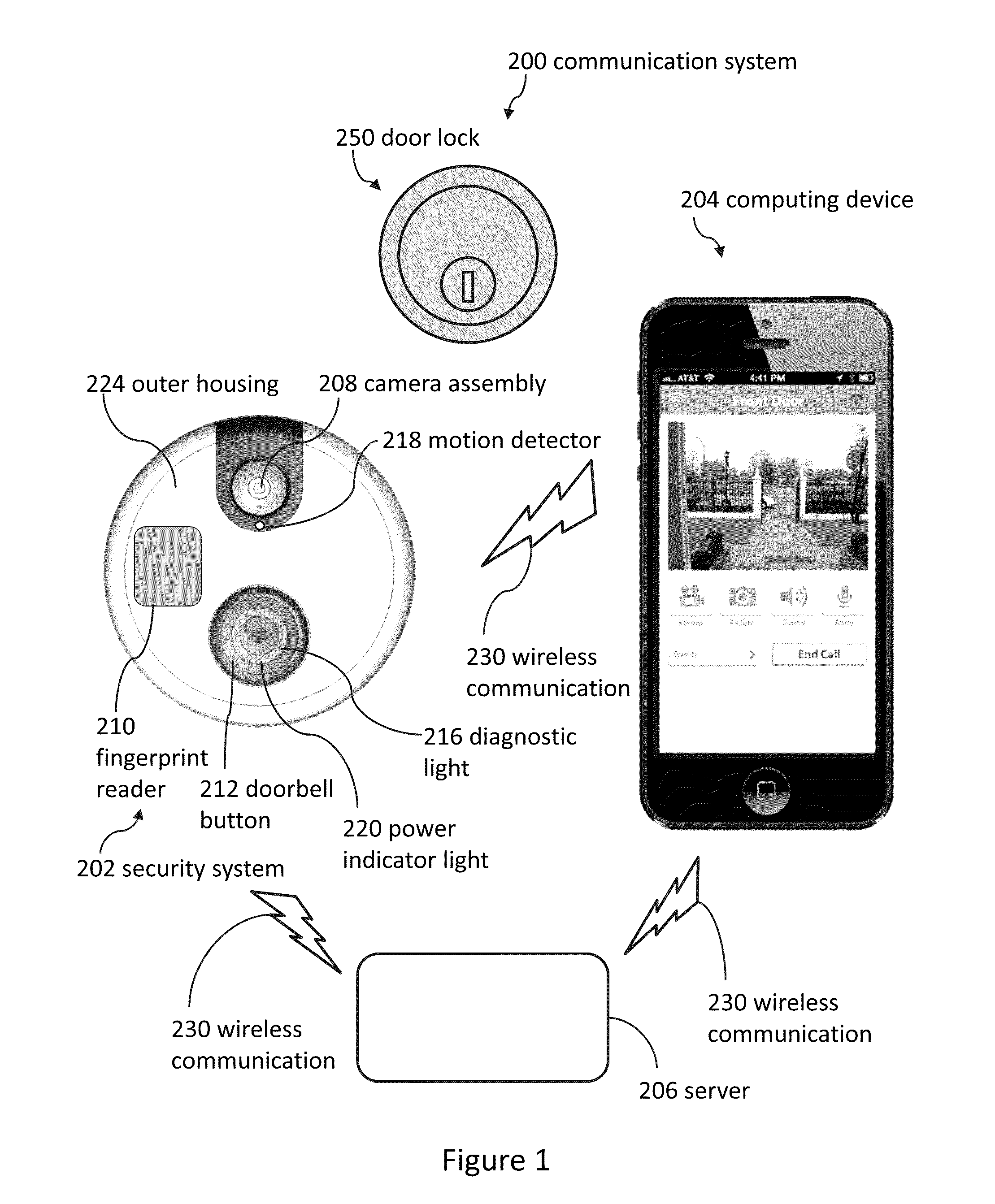
[0193]FIG. 9 illustrates a history 570 of lock-related events displayed on a user interface (e.g., of a smartphone, tablet, laptop, desktop computer, or television). The history can include when a door was locked and unlocked. The history can also include when the lock was set up and / or “paired” with the computing device 204 (show in FIG. 1).

[0194]Several embodiments comprise taking at least one image of the visitor on each occasion the visitor unlocks the lock 250; associating a time and a date with each additional image; and recording the additional images, the times, and the dates in the remote database 436. Methods can further comprise enabling the remote computing device 204 to display the images, the times, and the dates. For example, a user of the remote computing device 204 can search through the images to see the visitor who entered the building at a particular entry time (as captured in the history).

Watch Embodiments

[0195]FIG. 10 illustrates a front view of a computing dev...


PUM


Abstract

A door lock system can comprise a door lock movable between a locked state and an unlocked state. The door lock system can detect a first indication suggestive of a presence of a visitor. The door lock system can also detect a second indication suggestive of an identity of the visitor. As well, the door lock can validate that the first indication and the second indication are associated with a first identity.

Description

CROSS-REFERENCE TO RELATED APPLICATIONS[0001]This application claims the benefit of and is a continuation-in-part of U.S. Nonprovisional patent application Ser. No. 14 / 572,852; filed Dec. 17, 2014; and entitled SMART LOCK SYSTEMS AND METHODS. The entire contents of U.S. Nonprovisional patent application Ser. No. 14 / 572,852 are incorporated herein by reference.[0002]U.S. Nonprovisional patent application Ser. No. 14 / 572,852 claims the benefit of U.S. Provisional Patent Application No. 62 / 026,639; filed Jul. 19, 2014; and entitled WIRED HOME AUTOMATION METHODS AND SYSTEMS. The entire contents of U.S. Provisional Patent Application No. 62 / 026,639 are incorporated herein by reference.[0003]U.S. Nonprovisional patent application Ser. No. 14 / 572,852 also claims the benefit of U.S. Provisional Patent Application No. 62 / 018,606; filed Jun. 29, 2014; and entitled DOOR LOCK CHARGING SYSTEMS AND METHODS. The entire contents of U.S. Provisional Patent Application No. 62 / 018,606 are incorporated...

Claims


Application Information

Patent Timeline
Patent Type & Authority Applications(United States)
IPC IPC(8): G07C9/00E05B47/00
CPCY10T292/1021Y10T292/097Y10T70/7062Y10T70/5199E05B47/026G08B13/19684G07C9/00174G07C9/00563H04M11/025H04N7/188E05B2047/0059E05B2047/0061E05B2047/0095G07C2009/00634G07C2009/00769Y10T292/1014Y10T292/0969G07C9/00071E05B47/00G07C9/00309G06K9/00221H04N7/186H04W12/08G07C9/00087G07C9/00571G07C9/257G07C9/25G06V40/16
Inventor SCALISI, JOSEPH FRANK
Owner SKYBELL TECH IP LLC
Why Eureka
Try Eureka