

Compact transformer bushing
a transformer and bushing technology, applied in the direction of magnets, switchgear with a retractable carriage, magnetic bodies, etc., can solve the problems of increasing the material cost of the bushing, the larger the footprint, and the oversized bushing over which the current transformer is mounted usually cannot accommodate any tracking sheds, etc., to achieve a greater linear surface distance, increase the linear surface distance of the bushing, and shorten the shaft
- Summary
- Abstract
- Description
- Claims
- Application Information
AI Technical Summary
Benefits of technology
Problems solved by technology
Method used
Image

Examples
Embodiment Construction
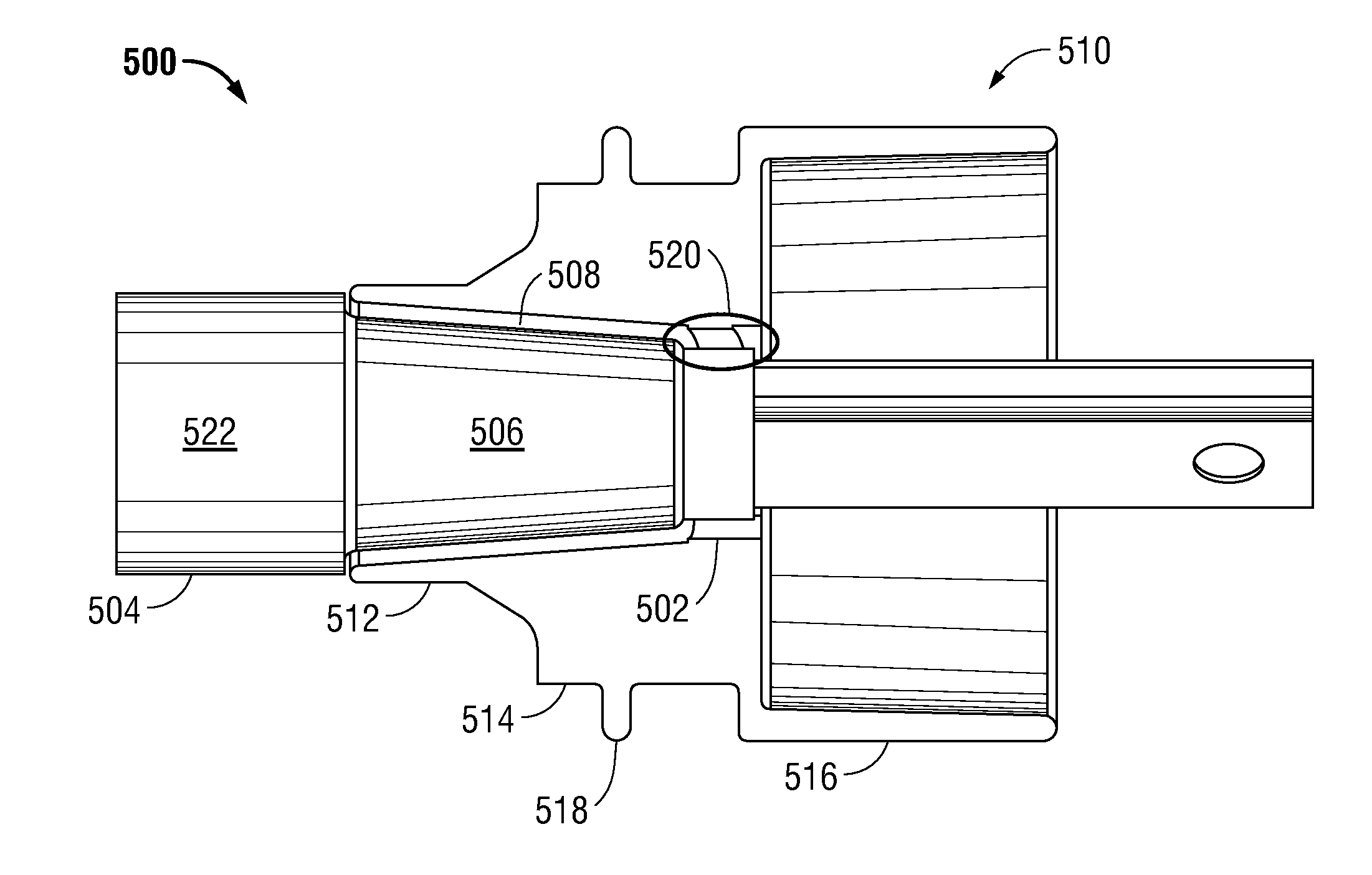
[0009]The disclosed embodiments address the above and other shortcomings of existing bushings by providing a compact bushing for electrical isolation equipment. The compact bushing has a separate insulating end cap that is removably attached to a shaft of the bushing at the end over which the current transformer is mounted. The removably attached insulating end cap has a large outer diameter that acts to increase the linear surface distance of the bushing. The specific outer diameter used may be selected or otherwise determined in a predefined manner based on the length of the shaft desired, and vice versa, with a larger outer diameter corresponding to a greater linear surface distance and a shorter shaft. The increased linear surface distance allows the bushing to meet minimum tracking requirements using a shorter shaft relative to existing bushings, which beneficially reduces the footprint of switchgear and other electrical isolation equipment to which the bushing may be connected...
PUM
| Property | Measurement | Unit |
|---|---|---|
| voltage | aaaaa | aaaaa |
| linear surface distance | aaaaa | aaaaa |
| length | aaaaa | aaaaa |
Abstract
Description
Claims
Application Information