
Ink jet printer and control method therefor

Active Publication Date: 2015-12-31
SEIKO EPSON CORP
View PDF3 Cites 0 Cited by
  • Summary
  • Abstract
  • Description
  • Claims
  • Application Information

AI Technical Summary

Benefits of technology

This invention provides an ink jet printer and method for controlling it that can prevent problems when ink is first ejected from a new ink storage unit. By reducing the amount of ink ejected in the initial stages, and ensuring that enough ink is fed to all nozzles, this technology prevents discharge failures and improves image quality.

Problems solved by technology

In the case of an ink storage member of a type in which the absorber is not used, it is possible to uniformize the concentration of the ink retained in the ink storage member to a certain degree by allowing a user to agitate the ink by means of, for example, shaking of the ink storage member, but in the case of an ink storage member of a foam type, it is difficult to eliminate variations in the concentration and the viscosity of the ink merely by means of the shaking of the ink storage member.
Thus, when the ink initially flown out from the newly attached ink storage member is ejected under the same condition as that for the desired ink, as a result, a lack of an amount of an ink to be fed to a nozzle arises, thereby sometimes causing a phenomenon in which a meniscus is not correctly formed inside the nozzle.
Further, this phenomenon is likely to cause a discharge failure, that is, a failure in that any ink is not ejected through the nozzle, or a failure in that, even though an ink is ejected through the nozzle, a direction of the ejected ink is deflected from a predetermined target direction.

Method used


Image

  • Ink jet printer and control method therefor
  • Ink jet printer and control method therefor
  • Ink jet printer and control method therefor

Examples


Embodiment Construction

[0022]Hereinafter, an embodiment in which the invention is practiced will be described with reference to the accompanying drawings. It is to be noted that an embodiment described below is a preferred specific example of the invention and thus includes various limitations, but the scope of the invention is not limited to such an embodiment described below except for a particular portion in the following description, in which a limitation of the invention is stated. Further, in the following, an ink jet image recording apparatus will be described as an example of the above ink jet printer according to the first aspect of the invention. In addition, hereinafter, this ink jet image recording apparatus will be referred to as just a printer.

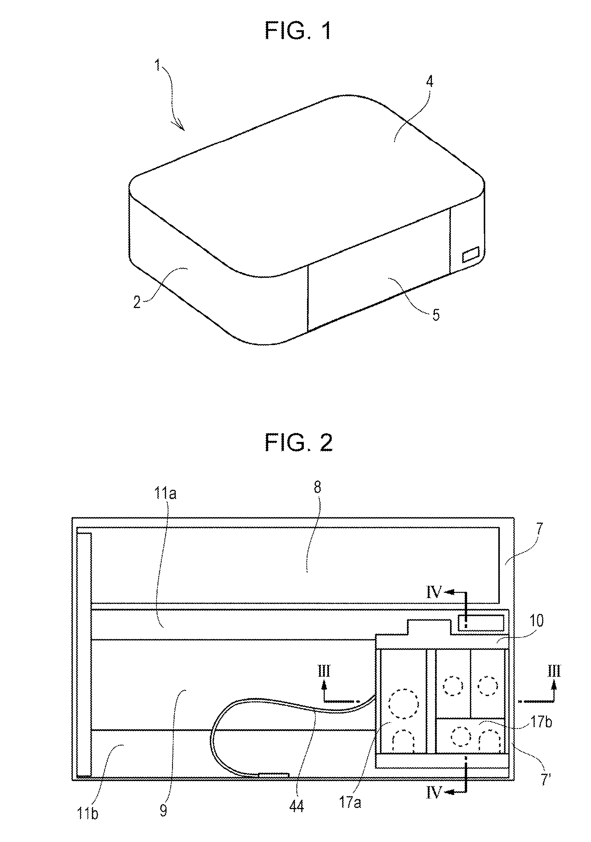
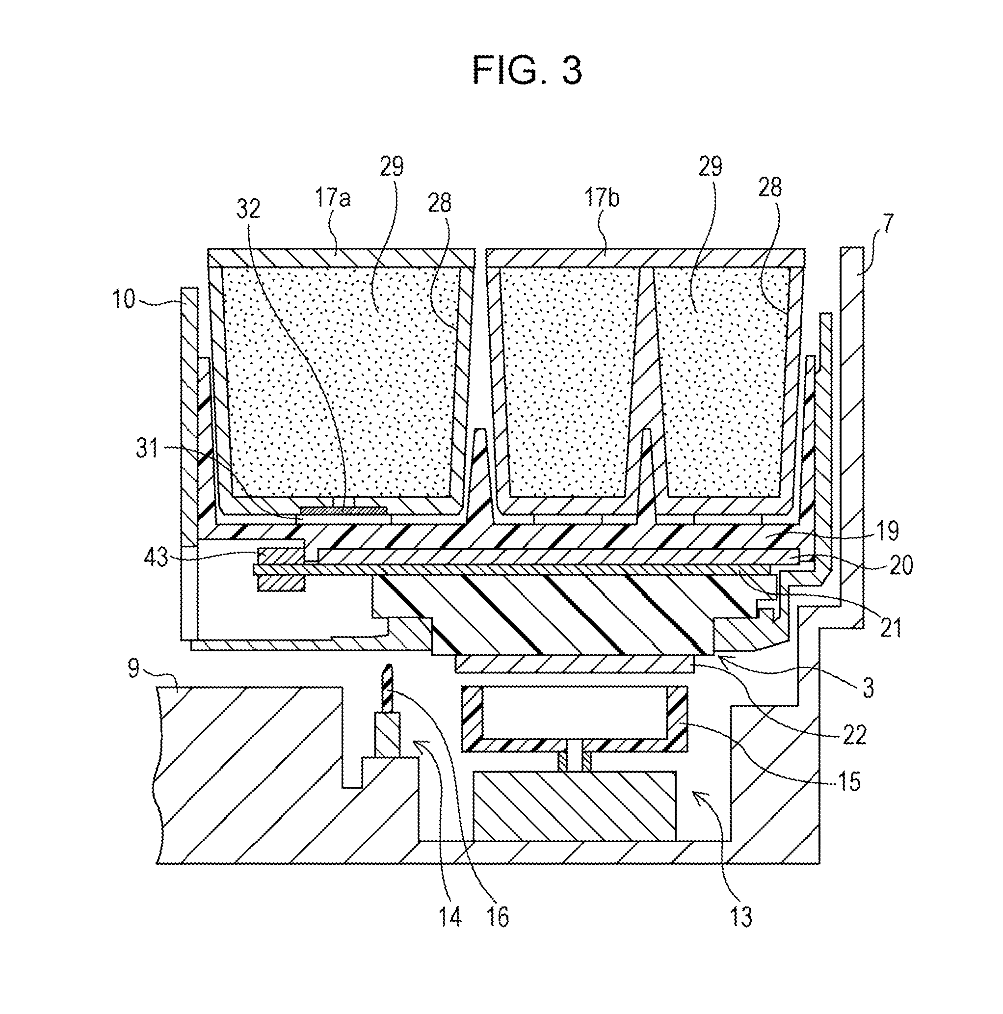
[0023]FIG. 1 is a perspective view that describes a configuration of an external view of a printer 1, and FIG. 2 is a plan view that describes an internal configuration of the printer 1. Further, FIG. 3 is a cross-sectional view taken along the line II...


PUM


Abstract

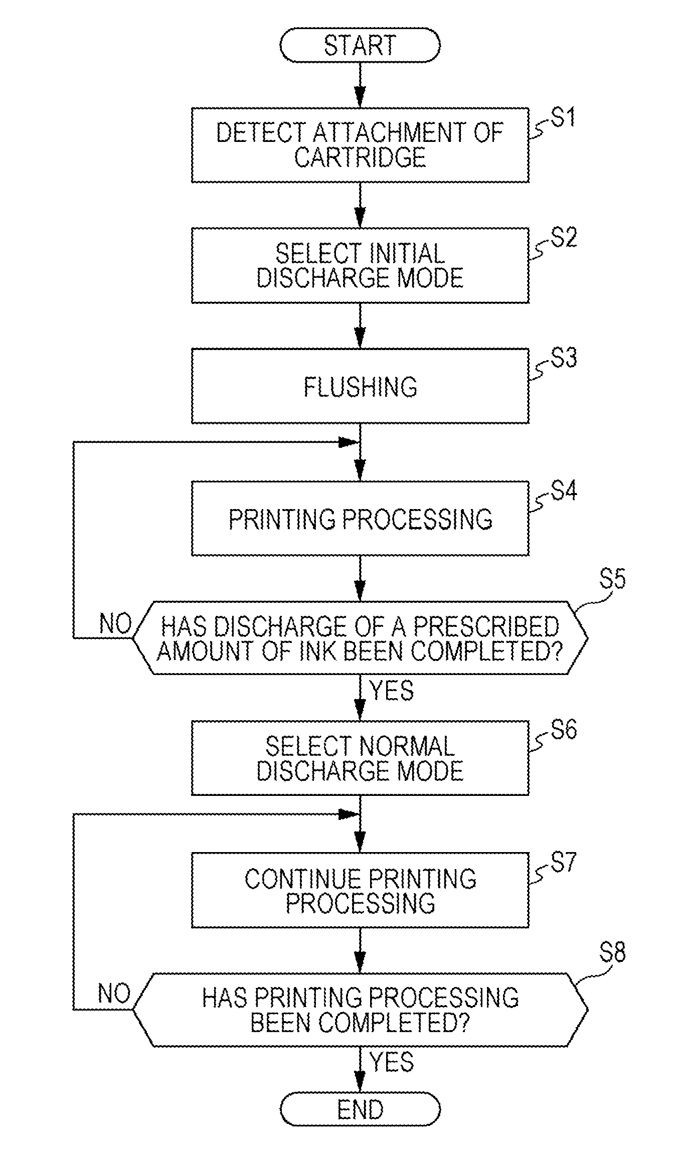
An ink jet printer includes an attachment detection portion that detects an attachment of an ink storage member that retains an ink in an absorber contained in the ink storage member itself; an ink jet recording head that ejects an ink flown in from the ink storage member; and a control circuit that controls ink ejection performed by the ink jet recording head. The control circuit is configured to, upon detection, by the attachment detection portion, of an attachment of the ink storage member to be newly used, perform control so as to cause a first operation mode to be set, and thereafter, perform control so as to cause the first operation mode to be switched to a second operation mode, upon satisfaction of a condition in that a total discharge amount of an ink ejected in the first operation mode reaches a prescribed amount. Further, a per-unit-time discharge amount of an ink ejected in the first operation mode is set so as to be smaller than a per-unit-time discharge amount of an ink ejected in the second operation mode.

Description

CROSS REFERENCE TO RELATED APPLICATIONS[0001]This application claims priority under 35 U.S.C. §119 to Japanese Patent Application No. 2014-129987 filed Jun. 25, 2014, the entire disclosures of which are expressly incorporated by reference herein.BACKGROUND[0002]1. Technical Field[0003]The present invention relates to ink jet printers and control methods therefor and, more particularly, an ink jet printer using an ink storage member that contains an absorber for absorbing and retaining an ink, and a control method therefor.[0004]2. Related Art[0005]An ink jet printer which belongs to a kind of ink jet printer is an apparatus that includes a permanent head and causes liquids of various kinds to be ejected (discharged) from the permanent head. This ink jet printer is a non-impact printing apparatus that forms characters on paper by ejecting particles or droplets of inks onto the paper (JIS X0012-1990). This ink jet printer is one of various forms of dot printers, this dot printer being...

Claims


Application Information

Patent Timeline
IPC IPC(8): B41J2/045
CPCB41J2/04551B41J2/04581B41J2/04588B41J2/0459B41J2/1752B41J2/17546B41J29/38B41J2/16508B41J2/1652B41J2/16526B41J2/16532B41J2/16538
Inventor HANAGAMI, TAIKIMATSUSHITA, JUNICHIROSEINO, TAKEO
Owner SEIKO EPSON CORP
Learn More