

Image processing device, image display apparatus, and image processing method
- Summary
- Abstract
- Description
- Claims
- Application Information
AI Technical Summary
Benefits of technology
Problems solved by technology
Method used
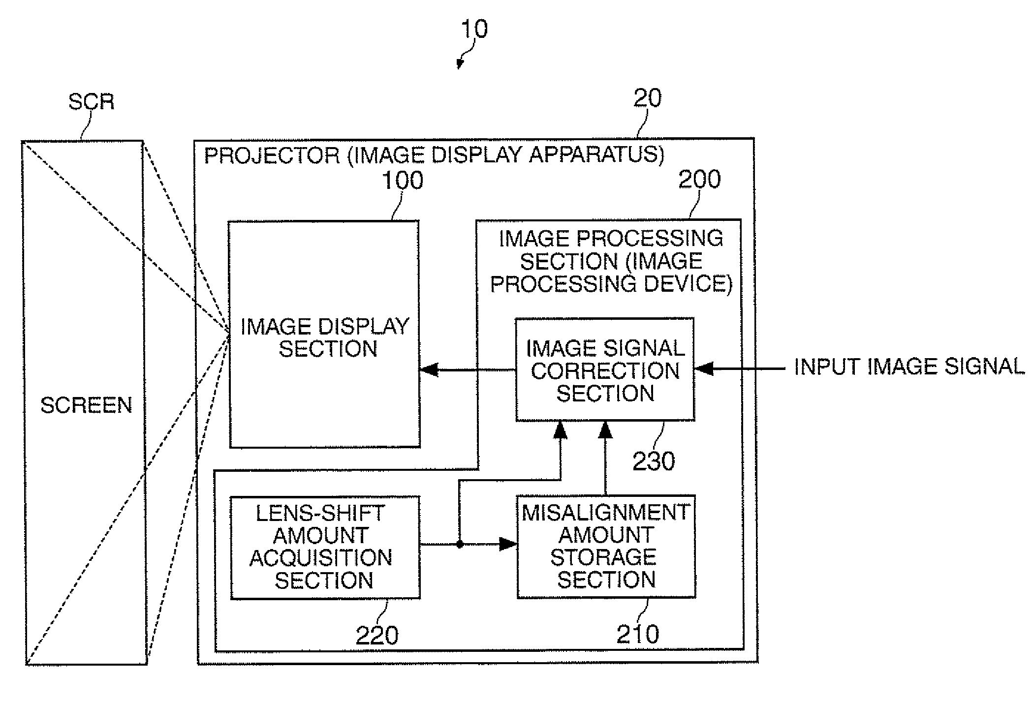
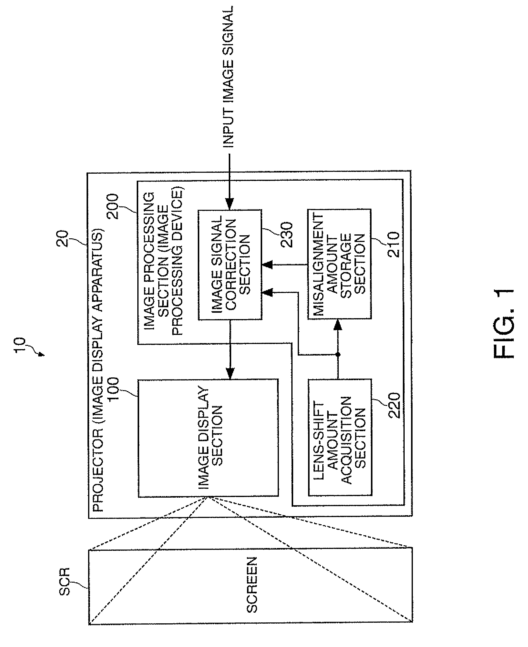
Image

Examples
first modified example
[0141]Although in the present embodiment the explanations are presented assuming that there are four reference positions, the invention is not limited thereto, but a configuration with two reference positions can also be adopted.
[0142]FIG. 18 is a diagram for explaining the reference positions in a first modified example of the present embodiment. In FIG. 18, the same sections as those in FIG. 4 are denoted with the same reference symbols, and explanations therefor are omitted if appropriate.
[0143]FIG. 19 shows the amounts of misalignment stored in the misalignment amount storage section in the first modified example of the present embodiment. In FIG. 19, the same sections as those in FIG. 5 are denoted with the same reference symbols, and explanations therefor are omitted if appropriate.
[0144]As shown in FIG. 18, the reference positions correspond to first and fourth pixel positions P1, P4 in the display screen DSP on the screen SCR by the projector 20. Specifically, the misalignme...
second modified example
[0147]Although in the present embodiment the explanations are presented assuming that there are four reference positions, the invention is not limited thereto, but a configuration with nine reference positions can also be adopted.
[0148]FIG. 20 is a diagram for explaining the reference positions in a second modified example of the present embodiment. In FIG. 20, the same sections as those in FIG. 4 are denoted with the same reference symbols, and explanations therefor are omitted if appropriate.
[0149]As shown in FIG. 20, the reference positions correspond to first through ninth pixel positions P1 through P9 in the display screen DSP on the screen SCR by the projector 20. Specifically, the misalignment amount storage section in the second modified example stores the amounts of misalignment at a first pixel position P1 at the upper left end of the display screen DSP, a second pixel position P2 at the upper right end thereof, a third pixel position P3 at the lower left end thereof, a fo...
third modified example
[0151]Although in the present embodiment the explanations are presented assuming that the amounts of misalignment at the reference positions are stored as described above for each of the nine levels of amounts of shift of the projection lens 170, the invention is not limited thereto, but it is also possible to store the amounts of misalignment at the reference positions for each of four levels of amounts of shift.
[0152]FIG. 21 is a diagram for explaining the amounts of shift at which the amounts of misalignment are stored to the misalignment amount storage section in a third modified example of the present embodiment. In FIG. 21, the same sections as those in FIG. 11 are denoted with the same reference symbols, and explanations therefor are omitted if appropriate.
[0153]FIG. 22 shows the amounts of misalignment stored in the misalignment amount storage section in the third modified example of the present embodiment. In FIG. 22, the same sections as those in FIG. 5 are denoted with th...
PUM
 Abstract
Description
Claims
Application Information