Video encoding method, video encoding device, video decoding method, video decoding device, program, and video system

Active Publication Date: 2018-12-06
NEC CORP
View PDF1 Cites 5 Cited by
  • Summary
  • Abstract
  • Description
  • Claims
  • Application Information

AI Technical Summary

Benefits of technology

[0026]According to the present invention, image quality degra

Problems solved by technology

In 8K, the processing load in the encoding process and the

Method used


Image

  • Video encoding method, video encoding device, video decoding method, video decoding device, program, and video system
  • Video encoding method, video encoding device, video decoding method, video decoding device, program, and video system
  • Video encoding method, video encoding device, video decoding method, video decoding device, program, and video system

Examples


Example

Example Embodiment 1

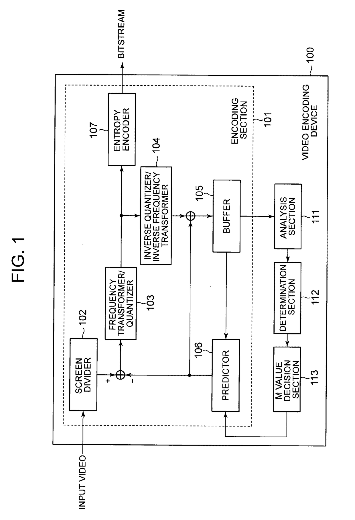
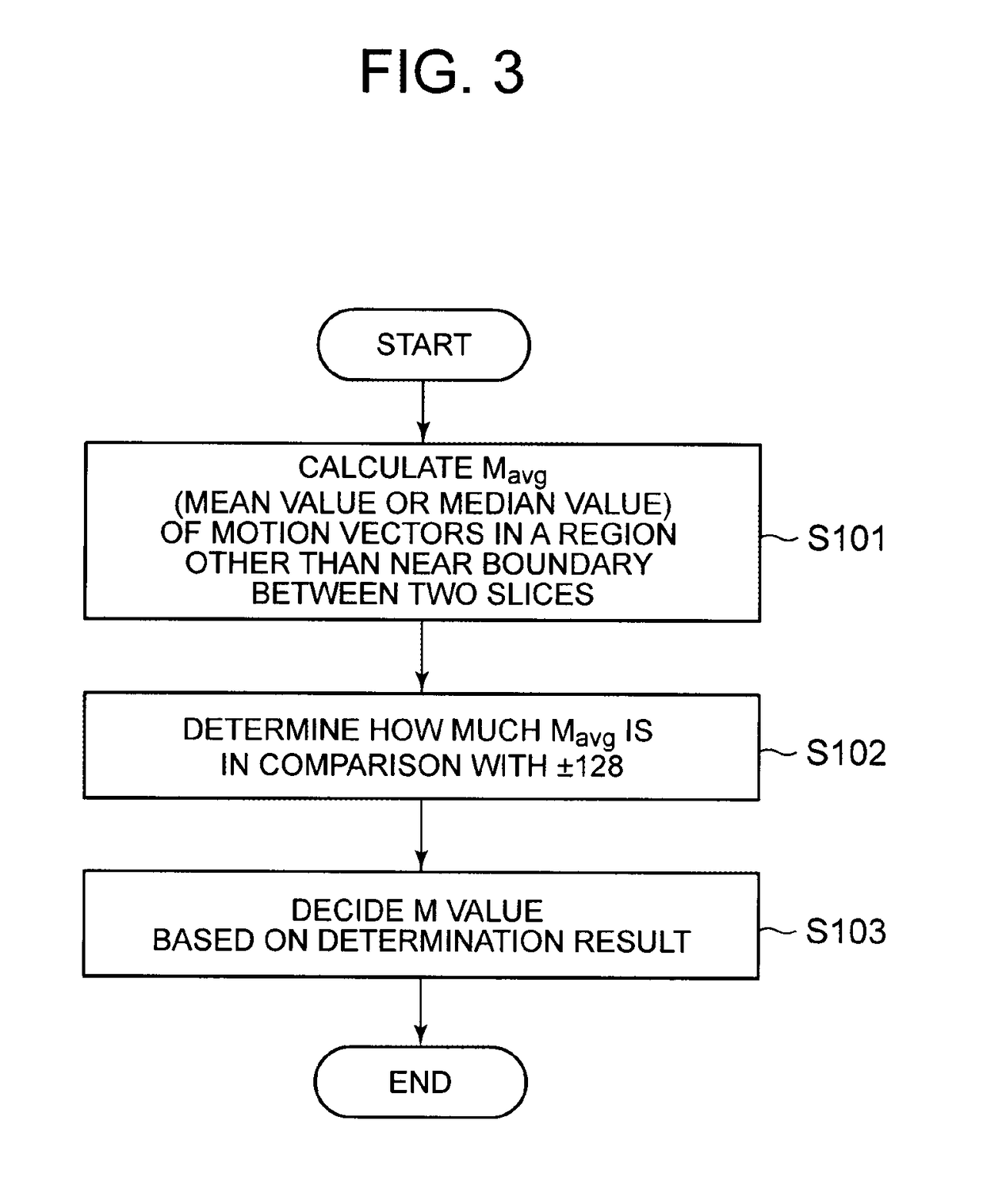
[0057]FIG. 3 is a flowchart depicting operation in example embodiment 1 of the video encoding device 100 depicted in FIG. 1. In example embodiment 1, it is assumed that 8K video is divided into four (see FIG. 11), and there is a motion vector restriction near a slice boundary. As the motion vector restriction, ±128 is used as an example. The case where 8K video is divided into four and there is a motion vector restriction also applies to the other example embodiments. An initial value of the M value is 8 (M=8).

[0058]The analysis section 111 analyzes the past encoding result (e.g. the encoding result of the immediately preceding frame) stored in the buffer 105. In detail, the analysis section 111 calculates the mean value or median value of the motion vectors in the blocks other than the slice boundary (the mean value or median value is hereafter denoted as Mavg) (step S101). In example embodiment 1, the encoding statistical information is the motion vector values...

Example

Example Embodiment 2

[0070]FIG. 4 is a flowchart depicting operation in example embodiment 2 of the video encoding device 100 depicted in FIG. 1.

[0071]The analysis section 111 analyzes the past encoding result (e.g. the encoding result of the immediately preceding frame) stored in the buffer 105. In detail, the analysis section 111 calculates a percentage P1 of blocks for which intra prediction (intra-screen prediction) is used, to all blocks (e.g. prediction units (PU)) in the range other than the slice boundary (step S201). The analysis section 111 also calculates a percentage P2 of blocks for which intra prediction is used, to all blocks near the slice boundary (step S202). In example embodiment 2, the encoding statistical information is the prediction modes (specifically, the number of intra prediction blocks) of blocks near the slice boundary, and the analysis result is the percentage P1 and the percentage P2.

[0072]The determination section 112 compares the percentage P1 and the...

Example

Example Embodiment 3

[0080]FIG. 5 is a flowchart depicting operation in example embodiment 3 of the video encoding device 100 depicted in FIG. 1.

[0081]The analysis section 111 analyzes the past encoding result (e.g. the encoding result of the immediately preceding frame) stored in the buffer 105. In detail, the analysis section 111 calculates a generated code amount C1 in blocks near the slice boundary of a preceding frame (e.g. a frame preceding the current frame to be encoded by two frames) (step S301). The analysis section 111 also calculates a generated code amount C2 in blocks near the slice boundary of the immediately preceding frame (step S302). In example embodiment 3, the encoding statistical information is the generated code amount in blocks near the slice boundary, and the analysis result is the generated code amount C1 and the generated code amount C2.

[0082]The determination section 112 compares the generated code amount C1 and the generated code amount C2, and determines...


PUM


Abstract

A video encoding device is a video encoding device for appropriately selecting a scalable encoding structure from a plurality of scalable encoding structures to generate a bitstream, using dynamic range-related video signal information, and includes an encoding section for selecting the scalable encoding structure capable of transmitting the dynamic range-related video signal information for switching a dynamic range, when a video signal to be encoded is switched from an SDR (a standard dynamic range) signal to an HDR (a high dynamic range) signal or switched from the HDR signal to the SDR signal in a temporal direction.

Description

TECHNICAL FIELD[0001]The present invention relates to a video encoding method, a video encoding device, a video decoding method, a video decoding device, a program, and a video system.BACKGROUND ART[0002]In response to demand for video of higher resolutions, Full HD (High Definition) video content of horizontal 1920×vertical 1080 (pixels) has been provided. In addition, test broadcasting and commercial broadcasting of high-definition video of horizontal 3840×vertical 2160 (pixels) (hereafter referred to as “4K”) have been started. Furthermore, commercial broadcasting of high-definition video of horizontal 7680×vertical 4320 (pixels) (hereafter referred to as “8K”) has been planned.[0003]In a video content distribution system, typically, a transmitter encodes a video signal based on the H.264 / AVC (Advanced Video Coding) standard or the HEVC (High Efficiency Video Coding) standard, and a receiver performs a decoding process to reproduce the video signal. In 8K, the processing load in ...

Claims


Application Information

Patent Timeline
IPC IPC(8): H04N19/70H04N19/30H04N19/103
CPCH04N19/70H04N19/30H04N19/103H04N19/31H04N19/114H04N19/136H04N19/177H04N19/102H04N19/124H04N19/139H04N19/159H04N19/146H04N19/176H04N19/174H04N19/46H04N19/184
Inventor ISHIDA, TAKAYUKICHONO, KEIICHI
Owner NEC CORP
Why Eureka
Try Eureka