
Systems, devices, and methods for wearable heads-up displays

a head-up display and head-mounted technology, applied in the field of electronic display technologies, can solve the problems of occupying the user's visual attention, limiting the ability to perform other tasks at the same time, and inconvenient to have one's hand(s) encumbered by the device itsel

Active Publication Date: 2015-12-31
GOOGLE LLC
View PDF7 Cites 81 Cited by
  • Summary
  • Abstract
  • Description
  • Claims
  • Application Information

AI Technical Summary

Benefits of technology

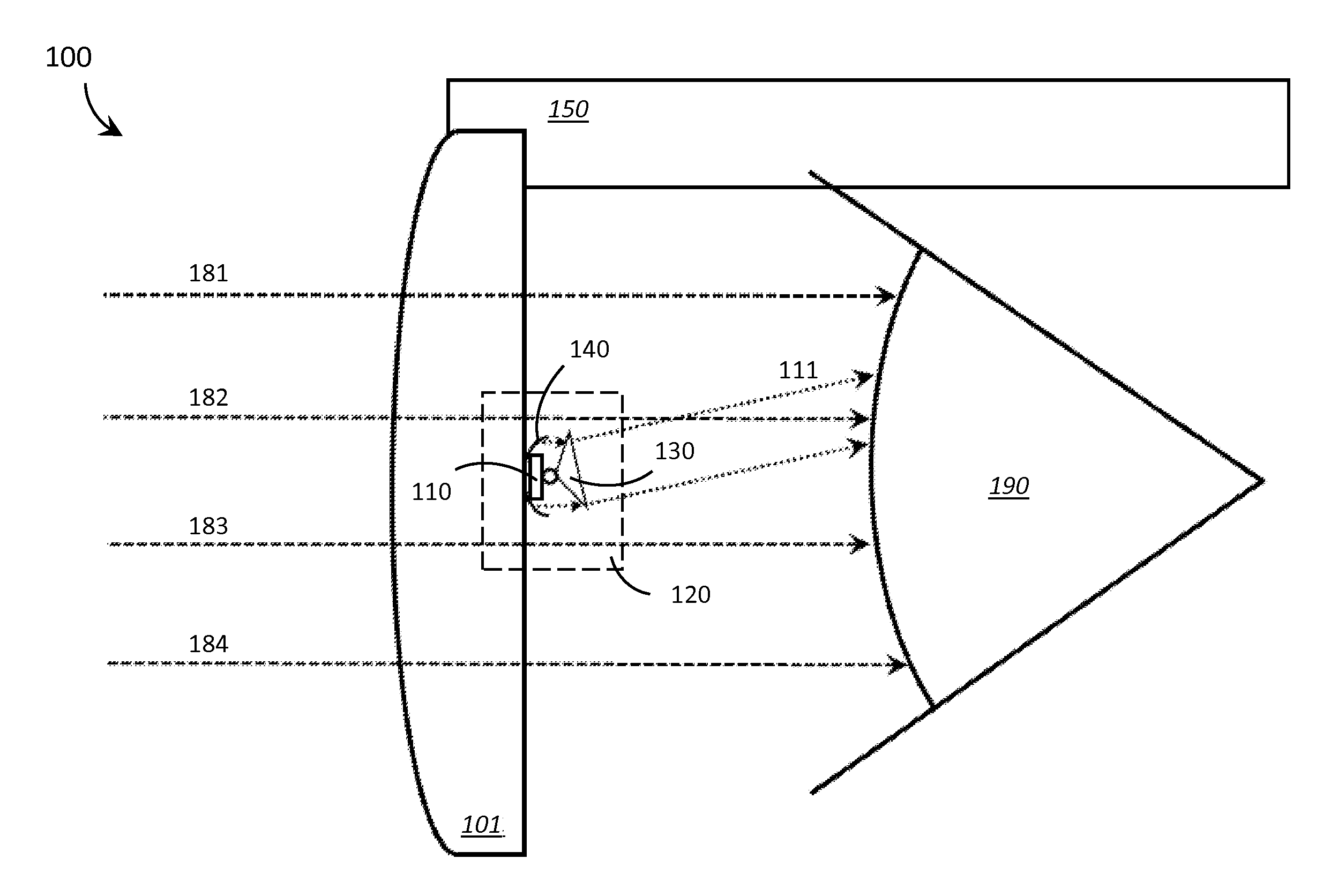
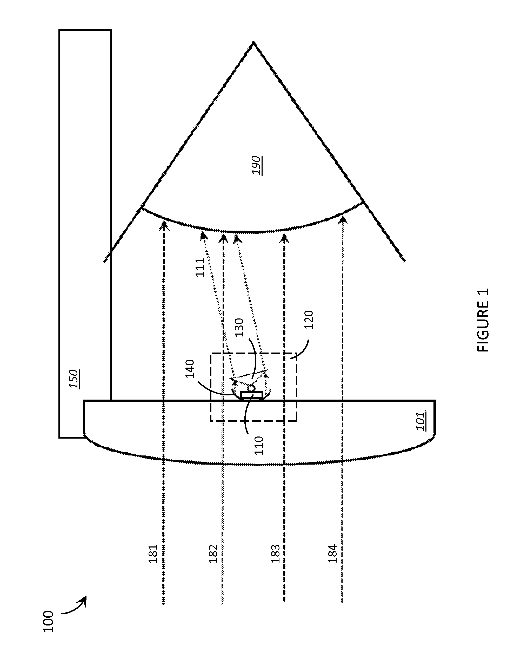
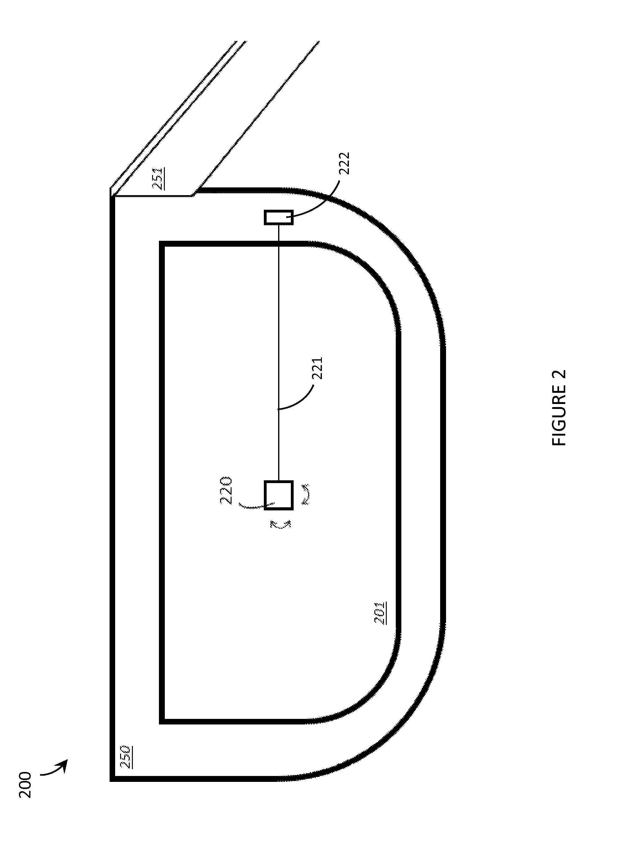
The patent describes a wearable heads-up display that includes a support structure that is worn on the user's head, a transparent element that is positioned in front of the user's eyes, and a scanning projector that is positioned on or near the transparent element. The scanning projector includes a light source, a collimator, and a controllable beam-steerer that can redirect light signals to specific regions of the user's eye. The wearable heads-up display can provide a realistic and immersive augmented reality experience for the user.

Problems solved by technology

However, the convenience of being able to carry a portable electronic device has also introduced the inconvenience of having one's hand(s) encumbered by the device itself.
Thus, even though the wearable nature of a wearable electronic device allows the user to carry and, to at least some extent, operate the device without occupying their hands, accessing and / or interacting with content presented on an electronic display of a wearable electronic device may occupy the user's visual attention and limit their ability to perform other tasks at the same time.
A wearable heads-up display is a head-mounted display that enables the user to see displayed content but does not prevent the user from being able to see their external environment.
A challenge in the design of most wearable heads-up display devices is the need to provide focused, high-quality images to the user without limiting the user's ability to see their external environment, and while at the same time minimizing the bulk of the wearable heads-up display unit itself.

Method used


Image

  • Systems, devices, and methods for wearable heads-up displays
  • Systems, devices, and methods for wearable heads-up displays
  • Systems, devices, and methods for wearable heads-up displays

Examples


Embodiment Construction

[0040]In the following description, certain specific details are set forth in order to provide a thorough understanding of various disclosed embodiments. However, one skilled in the relevant art will recognize that embodiments may be practiced without one or more of these specific details, or with other methods, components, materials, etc. In other instances, well-known structures associated with portable electronic devices and head-worn devices, have not been shown or described in detail to avoid unnecessarily obscuring descriptions of the embodiments.

[0041]Unless the context requires otherwise, throughout the specification and claims which follow, the word “comprise” and variations thereof, such as, “comprises” and “comprising” are to be construed in an open, inclusive sense, that is as “including, but not limited to.”

[0042]Reference throughout this specification to “one embodiment” or “an embodiment” means that a particular feature, structures, or characteristics may be combined ...


PUM


Abstract

Systems, devices, and methods for transparent displays that are well-suited for use in wearable heads-up displays are described. Such transparent displays include one or more scanning projector(s) that is / are mounted on or proximate the lens portion(s) thereof, directly in the field of view of the user. Each scanning projector includes a respective light source that sequentially generates pixels or other discrete portions of an image and a respective dynamic optical beam-steerer that controllably steers the modulated light directly towards select regions of the eye of the user. Successive portions of the image are generated in rapid succession until the entire image is displayed to the user by projection directly onto the eye of the user from one or more point(s) within the user's field of view.

Description

BACKGROUND[0001]1. Technical Field[0002]The present systems, devices, and methods generally relate to electronic display technologies and particularly relate to electronic display technologies that are well-suited for use in wearable heads-up displays.[0003]2. Description of the Related ArtWearable Electronic Devices[0004]Electronic devices are commonplace throughout most of the world today. Advancements in integrated circuit technology have enabled the development of electronic devices that are sufficiently small and lightweight to be carried by the user. Such “portable” electronic devices may include on-board power supplies (such as batteries or other power storage systems) and may be designed to operate without any wire-connections to other, non-portable electronic systems; however, a small and lightweight electronic device may still be considered portable even if it includes a wire-connection to a non-portable electronic system. For example, a microphone may be considered a port...

Claims


Application Information

Patent Timeline
Patent Type & Authority Applications(United States)
IPC IPC(8): G02B27/01G02B27/00G02C11/00G02B27/30G02B26/10
CPCG02B2027/0178G02B27/30G02B26/10G02B2027/0187G02B2027/015G02B2027/0154G02B27/017G02B27/0176
Inventor BAILEY, MATTHEWALEXANDER, STEFAN
Owner GOOGLE LLC
Learn More