Method and apparatus for high pressure water treatment of the inside of a pipe section

a technology for treating the inside of the pipe and the pipe section, which is applied in the direction of cleaning processes and apparatus, cleaning of hollow articles, corrosion prevention, etc., can solve the problems of significant amount of water and other debris, wear or deterioration of the lining of the pipeline, and inconvenient use of in-pipe robots or tractors

Active Publication Date: 2016-01-14
MAC & MAC HYDRODEMOLITION
View PDF3 Cites 14 Cited by
  • Summary
  • Abstract
  • Description
  • Claims
  • Application Information

AI Technical Summary

Benefits of technology

[0018]In a further aspect of the invention, there may be provided an exit support platform for supporting the working end of the boom as it is being withdrawn from the pipe, but while the nozzle(s) have not yet completely removed the liner near the end of the pipe. The exit platform provides a support surface for the removable wheel to roll onto at a height that matches the liner surface on which the support wheel rests. The exit platform may further comprise additional support surfaces at suitable elevations and angles for enabling the additional support wheels to rest against the additional support surfaces when the working end of the boom is exiting the pipe.

Problems solved by technology

The use of in-pipe robots or tractors is inconvenient in the case of pipe sections that are short and small enough to be transported to a remote location to be treated.
The lining of the pipelines wears or deteriorates over time, and it becomes necessary to periodically remove and replace the affected pipe segments in the pipeline.
The use of high and ultra-high pressure water results in a significant amount of water and other debris (including shredded liner or pieces of liner), being displaced within the pipe, as well as introducing significant lateral stresses on the nozzle assemblies.

Method used


Image

  • Method and apparatus for high pressure water treatment of the inside of a pipe section
  • Method and apparatus for high pressure water treatment of the inside of a pipe section
  • Method and apparatus for high pressure water treatment of the inside of a pipe section

Examples


Embodiment Construction

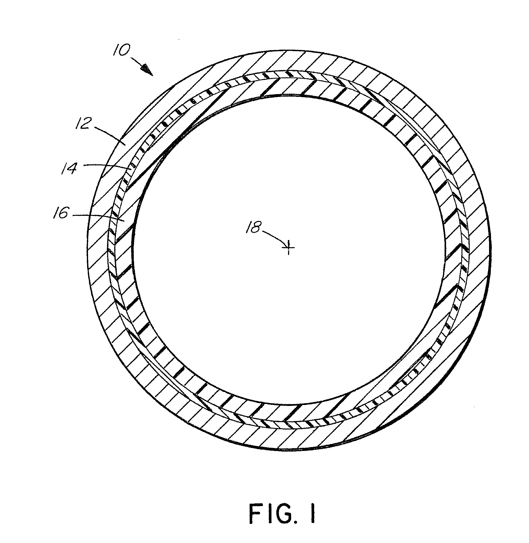
[0044]Referring to FIG. 1, a section of pipe 10 comprises an inside wall 12 having a layer of rubber 14 adhered to the interior surface of the wall 12 and a layer of urethane 16 adhered to the rubber layer 14. In FIG. 1, the wall 12, the rubber layer 14 and the urethane layer 16 appear as concentric rings about a central pipe axis 18. Pipe segments of the kind illustrated are used in pipelines for conveying diluted bitumen after it has been extracted from oil sands to a storage / shipping facility or refinery. Typically, the pipe segments are about 50 feet long. As well, depending on the application of the pipeline, the pipe segments may comprise only one layer of lining material, or they may have a plurality of layers or lining material. Two layers are disclosed in relation to the preferred embodiment but aspects of the invention may be practiced with a single layer or more than two layers of various materials. While the present invention is described and illustrated in application t...


PUM

PropertyMeasurementUnit
thickaaaaaaaaaa
lengthaaaaaaaaaa
lengthaaaaaaaaaa

Abstract

Material lining the inside surface of a section of pipe is removed by a hydrodemolition nozzle assembly mounted on a working end of an elongated boom. The opposed end of the boom is supported outside the pipe on a movable support for inserting and retracting the boom from the inside of the pipe. The nozzles remove the liner while the working end of the boom is supported by a wheel resting on the liner that has not yet been removed and that rolls along the inside liner as the pipe is made to revolve around the boom. The nozzles are oriented to eject the liner and water downstream and away from the boom.

Description

FIELD OF THE INVENTION[0001]This invention relates to a method and apparatus for treating the inside of a section of pipe to remove liners by hydrodemolition.BACKGROUND OF THE INVENTION[0002]Removing degraded coatings and liners is the first step to reconditioning the inside surface of a pipe and is performed before new coatings or liners are applied. The inside surfaces of some larger pipes may be reconditioned while the pipes remain in the ground. Such may be the case for example for sewer pipes. In other cases, for example removing and replacing the insider liners of oil pipelines, sections of pipe are removed from the pipeline, collected and delivered to be reconditioned at a remote location.[0003]High pressure water may be used to remove the inside liners of pipes by hydrodemolition, namely by fluid blasting the exposed surface to disintegrate and remove the liners. In the case of embedded or installed pipes, it is generally known to mount hydrodemolition nozzles on robots or t...

Claims


Application Information

Patent Timeline
Patent Type & Authority Applications(United States)
IPC IPC(8): B08B9/032B08B9/043F16L55/18F16L57/06F16L58/02
CPCB08B9/0433F16L57/06B08B9/0321F16L55/18F16L58/02F16L58/1027B08B9/00B08B3/04B08B9/032B08B3/02B08B3/00B08B3/024B08B9/021B08B1/00B08B9/04B08B9/027
Inventor MACNEIL, GERARD J.MACNEIL, DAVID B.MACNEIL, GORDONBOSE, VERNONMACNEIL, JESSEMACNEIL, BRETT
Owner MAC & MAC HYDRODEMOLITION
Why Eureka
Try Eureka