Spectacle lens design system, supply system, design method and manufacturing method

a technology of supply system and spectacle lens, applied in the field of designing and manufacturing spectacle lens, can solve the problems of blur, shaking or distortion, and the inability to simply introduce the measurement technology of visual lines into the design of spectacle lenses, and achieve the effect of preventing the occurrence of an error of direction and distance of visual lines

Active Publication Date: 2016-01-14
HOYA CORP
View PDF3 Cites 34 Cited by
  • Summary
  • Abstract
  • Description
  • Claims
  • Application Information

AI Technical Summary

Benefits of technology

[0008]It is considered that one of factors which cause, particularly during near vision, blur, shake, distortion and the like on the spectacle lens designed using visual line information measured by visual line measurement technology described in non-patent document 1 is the fact that a start point (a corneal apex) of the visual line information is different from an origin (the eyeball rotation center) defined in design of the spectacle lens. For this reason, in the embodiment of the invention, the visual line information is calculated while setting the start point of the visual line information at the eyeball rotation center which is equal to the origin defined in the design of the spectacle lens. By designing the spectacle lens using such visual line information, it is possible to prevent occurrence of an error of a direction and a distance of a visual line caused by the difference between the start point of the visual line information and the origin defined in design of the spectacle lens. That is, according to the embodiment of the invention, by using the above described visual line information, the spectacle lens having the aberration distribution suitable for each visual line information can be designed.
[0020]In the embodiment of the invention, the visual line information is calculated while setting the start point of the visual line information at the eyeball rotation center which is equal to the origin defined in the design of the spectacle lens. By designing the spectacle lens using such visual line information, it is possible to prevent occurrence of an error of a direction and a distance of a visual line caused by the difference between the start point of the visual line information and the origin defined in design of the spectacle lens. That is, according to the embodiment of the invention, by using the above described visual line information, the spectacle lens having the aberration distribution suitable for each visual line information can be designed.

Problems solved by technology

As a result, the inventor has found that it is impossible to simply introduce the measurement technology for visual lines described in the non-patent document 1 into design of spectacle lenses.
Specifically, when spectacle lenses are designed using visual line information measured by the measurement technology for visual lines described in the non-patent document 1, if simulation in which a scheduled wearer performs near vision (e.g., reading) in a state of wearing spectacle lenses is executed, blur, shaking or distortion occurs.
Therefore, it is found that aberration distribution suitable for visual lines for near vision is not achieved.

Method used


Image

  • Spectacle lens design system, supply system, design method and manufacturing method
  • Spectacle lens design system, supply system, design method and manufacturing method
  • Spectacle lens design system, supply system, design method and manufacturing method

Examples


example 3

[0164]In the following, the example 3 regarding a visual line information collecting process is explained. As explained in detail below, in the example 3, wearing parameters are collected simultaneously and in series with the visual line information while considering the pose of the head of the scheduled wearer S. It should be noted that, in the example 3, explanations overlapping with those of the example 1 are omitted or simplified. Furthermore, in the example 3, to configurations and steps which are substantially the same as those of the example 1, the same reference numbers are assigned and explanation thereof is omitted or simplified.

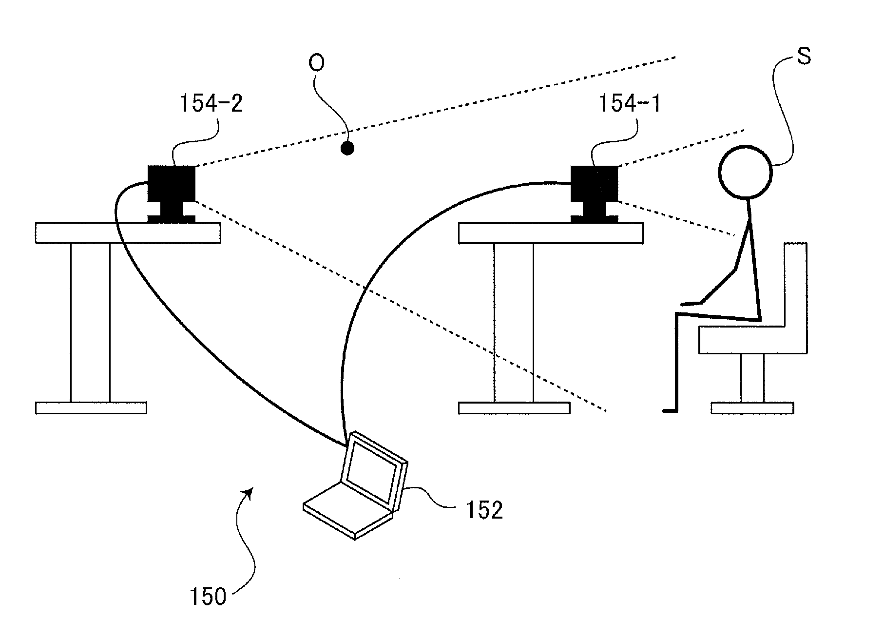
[0165]FIG. 14 illustrates a use condition of a visual line information collecting apparatus 150N according to the example 3. Since the configuration of the visual line information collecting apparatus 150N of the example 3 is the same as the configuration (FIG. 11) in the example 2, explanation thereof is omitted. As shown in FIG. 14, the visual li...

example 1

DESIGN EXAMPLE 1

[0228]FIG. 25A shows transmission astigmatism distribution of a lens before optimization according to the design example 1, and FIG. 25B shows transmission astigmatism distribution of a lens after optimization according to the design example 1. In the design example 1, the evaluation function is defined such that the transmission astigmatism becomes lower than or equal to 2.0 diopter (2.0D) within the use region (a region surrounded by an ellipse in FIGS. 25A and 25B) calculated in step S203 (calculation of use region and use frequency) in FIG. 23. As shown in FIG. 25B, since the transmission astigmatism is suppressed to a value lower than or equal to 2.0D in the use region, shake and distortion in the use region are reduced.

example 2

DESIGN EXAMPLE 2

[0229]FIG. 26A shows distribution of logMAR visual acuity before optimization according to the design example 2, and FIG. 26B shows distribution of logMAR visual acuity after optimization according to the design example 2. Details about logMAR visual acuity can be seen, for example, in Japanese Patent Publication No. 4033344B. In the design example 2, the evaluation function is defined such that, within the use region in a distance portion situated on an upper side of the fitting point FP on the lens, an area in which the logMAR visual acuity becomes lower than or equal to 0.155 (0.7 or more in terms of decimal visual acuity) becomes larger than 190 mm2 on the basis of an area on the distribution diagram (not on the basis of an area on the lens). As shown in FIG. 26B, in the design example 2, assuming a situation where a far point is mainly viewed, for example, during car driving, a wide range in which the scheduled wearer S can clearly recognize an object within the...


PUM


Abstract

A spectacle lens design system, including: an eyeball rotation center determination means that identifies an corneal apex position of an eye of a subject based on an image photographed by a predetermined photographing apparatus and determines an eyeball rotation center position of the subject based on the identified corneal apex position; a visual line information calculation means that calculates visual line information of the subjected defined when the subject watches a visual target disposed at a predetermined position, based on the eyeball rotation center position determined by the eyeball rotation center determination means and the position of the visual target; and a shape design means that designs a shape of a spectacle lens based on predetermined prescription information and the visual line information calculated by the visual line information calculation means.

Description

TECHNICAL FIELD[0001]The present invention relates a method for designing and manufacturing spectacle lenses using visual line information of a subject.BACKGROUND ART[0002]Recently, introducing visual line information of a scheduled wearer into design of spectacle lenses has been proposed in order to provide spectacle lenses more suitable for a customer (a scheduled wearer or a subject). A specific design method for such spectacle lenses is described, for example, in Japanese Patent Publication No. 4942661B (hereafter, referred to as patent document 1).[0003]However, the design method described in patent document 1 is based on the premise that a scheduled wearer is supposed to wear spectacle lenses when measurement of visual lines is performed. Therefore, a problem that the design method is not able to support a scheduled wearer of naked eyes is pointed out.SUMMARY OF THE INVENTION[0004]Non-patent document 1 (Kenneth Alberto Funes Mora and Jean-Marc Odobez: “Gaze Estimation from Mul...

Claims


Application Information

Patent Timeline
Patent Type & Authority Applications(United States)
IPC IPC(8): G02C13/00A61B3/11G02C7/02
CPCG02C13/005G02C7/027A61B3/111G02C7/024G02C7/06A61B3/152G02C7/025G02C7/061A61B3/0091A61B3/113
Inventor NISHIMURA, HIDETOSHIODAIRA, TOMOHIRO
Owner HOYA CORP
Why Eureka
Try Eureka