Antenna apparatus having patch antenna

a technology of patch antenna and antenna, which is applied in the structure of radiating elements, substantially flat resonant elements, and resonant antennas, etc., can solve the problems of disturbance in the directivity of the patch antenna and affect the performance of the patch antenna, so as to achieve the effect of suppressing disturbance in directivity and retaining desired beam width

Active Publication Date: 2016-01-28
DENSO CORP
View PDF3 Cites 24 Cited by
  • Summary
  • Abstract
  • Description
  • Claims
  • Application Information

AI Technical Summary

Benefits of technology

[0023]Therefore, in the antenna apparatus, the conductive structures are arranged to form the structure absent region. As a result, the transmission distance of the surface current can be ensured and the desired beam width can be retained. In addition, the structure absent region is formed (the conductive structures are arranged) such that the absent distance in the structure absent region differs depending on the position on the patch line. As a result, the radiation position for radiation attributed to surface current can be dispersed and disturbance in directivity can be suppressed.

Problems solved by technology

The emission from the substrate end portions caused by the surface current is unnecessary emission that affects the performance of the patch antenna.
In other words, the emission from the end portions causes disturbance in the directivity of the patch antenna.

Method used


Image

  • Antenna apparatus having patch antenna
  • Antenna apparatus having patch antenna
  • Antenna apparatus having patch antenna

Examples


first embodiment

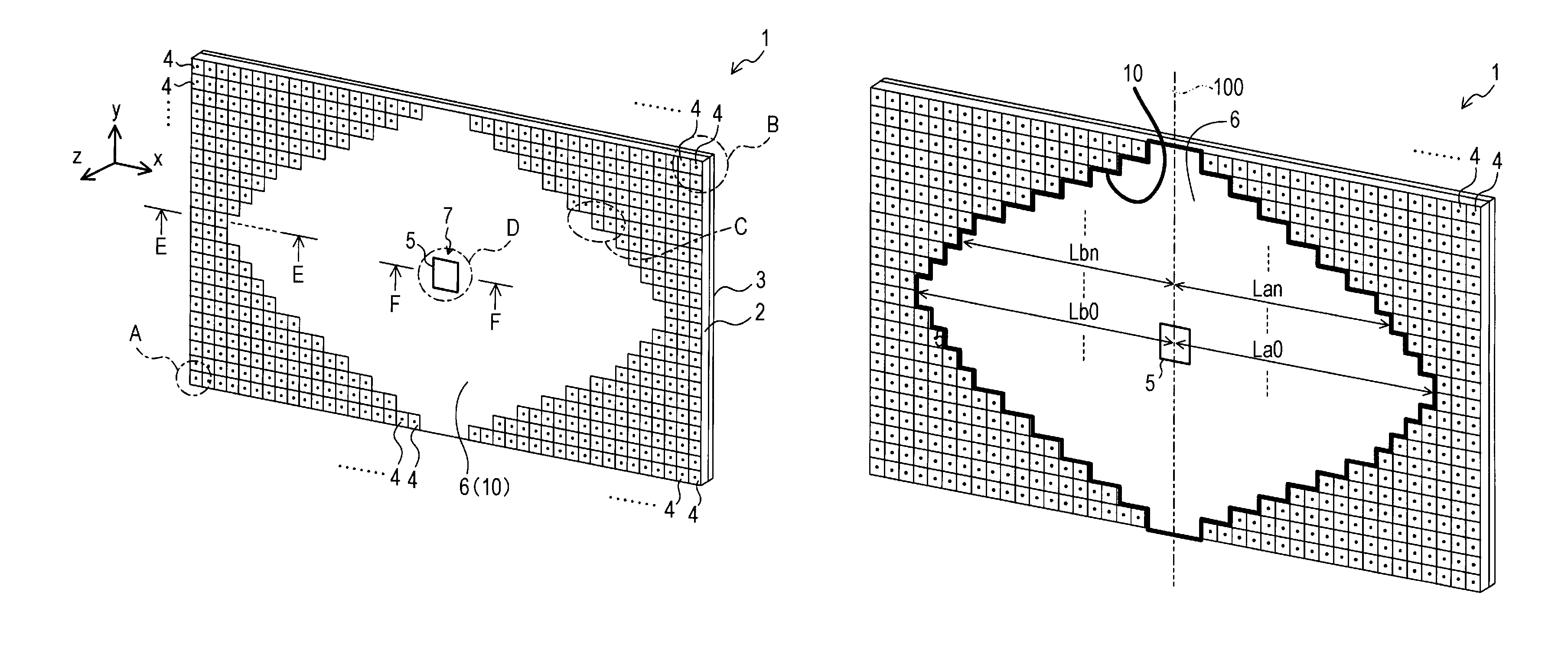
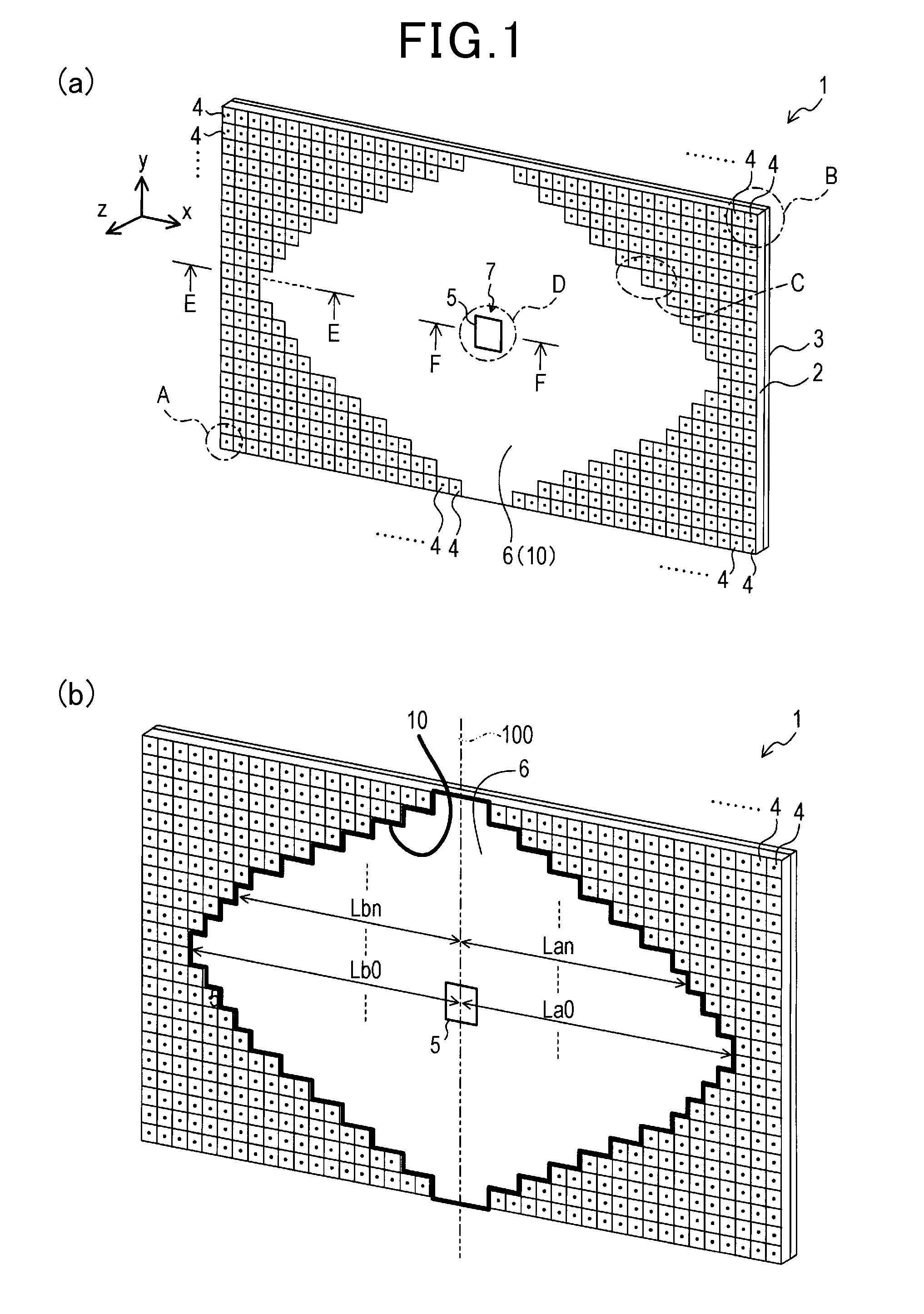
[0039]As shown in FIG. 1(a), an antenna apparatus 1 according to the present embodiment is configured such that a patch antenna 7, a conductor plate 6, and a plurality of electromagnetic band gaps (EBGs) 4 are formed on one surface (substrate front surface) of a rectangular dielectric substrate 2. A ground plate (ground plane) 3 composed of a conductor is formed on the other surface (substrate back surface) of the dielectric substrate 2. In the description hereafter, the long-side direction (lateral direction in FIG. 1(a)) of the dielectric substrate 2 is referred to as an x-axis direction. The short-side direction (vertical direction in FIG. 1(a)) of the dielectric substrate 2 is referred to as a y-axis direction. The direction perpendicular to the substrate face of the dielectric substrate 2 is referred to as a z-axis direction.

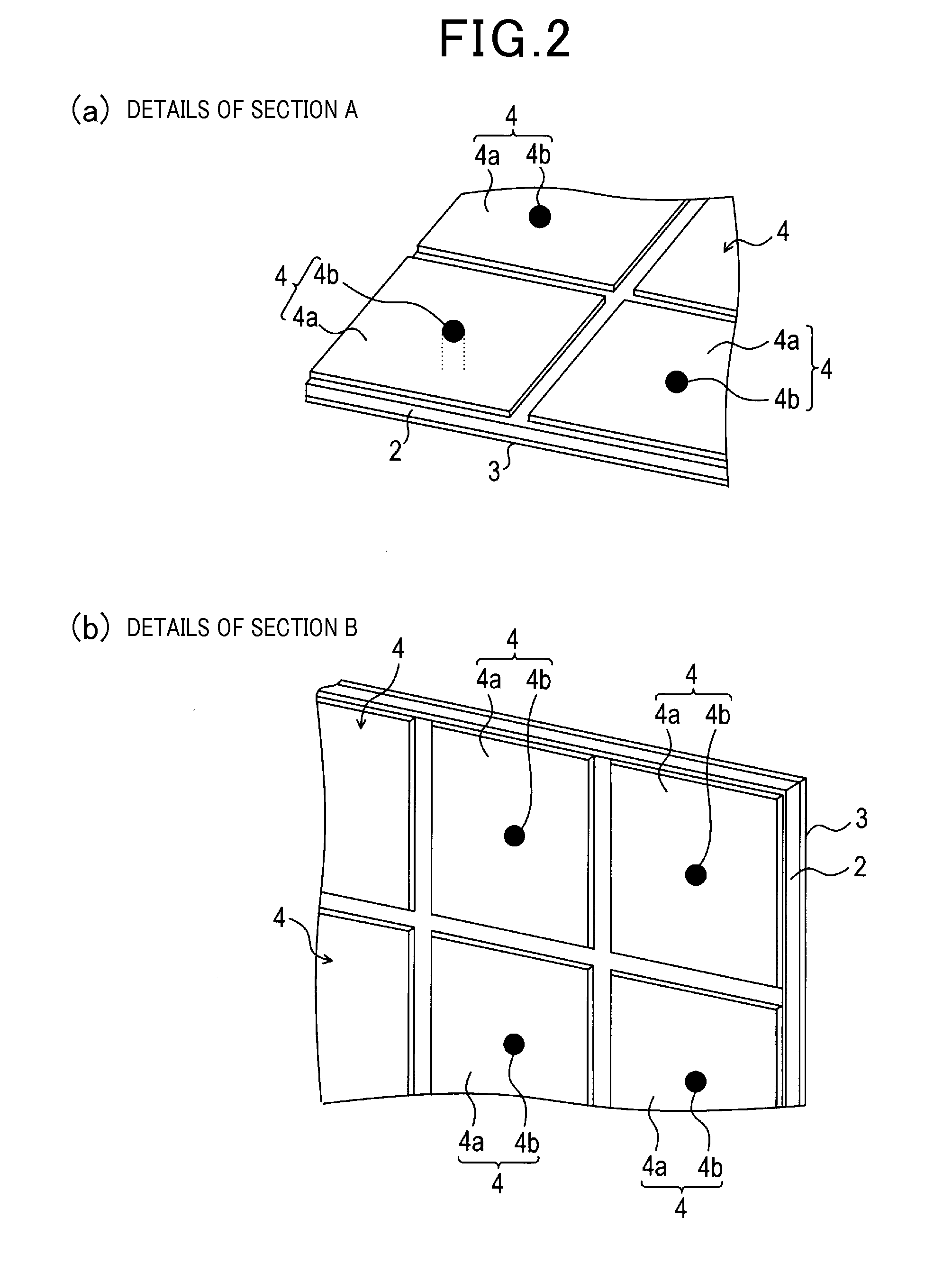
[0040]FIG. 2(a) and FIG. 2(b) show detailed (enlarged) views of section A and section B, which are indicated by broken-line circles, in the antenna apparat...

second embodiment

[0060]An antenna apparatus 20 according to a second embodiment shown in FIG. 5 differs from the antenna apparatus 1 according to the first embodiment shown in FIG. 1 in terms of the configuration of a patch antenna 25. That is, whereas the patch antenna 7 according to the first embodiment is provided with a single patch radiating element 5, the patch antenna 25 according to the present embodiment is configured such that a plurality (four, in the present embodiment) of patch radiating elements 21, 22, 23, and 24 are arrayed at a predetermined interval in the vertical direction (y-axis direction) in the center portion of the dielectric substrate 2.

[0061]The shape and size of each patch radiating element 21 to 24 are the same as those of the patch radiating element 5 according to the first embodiment. According to the present embodiment, power supply to the patch radiating elements 21 to 24 is configured such that a microstrip line for power supply is branched and the patch radiating e...

third embodiment

[0069]An antenna apparatus 30 according to a third embodiment shown in FIG. 7 differs from the antenna apparatus 20 according to the second embodiment shown in FIG. 5 in terms of the patch radiating elements being formed on both the left and right sides of the patch antenna 25. The antenna apparatus 30 according to the third embodiment is the same as the antenna apparatus 20 according to the second embodiment in terms of other aspects.

[0070]That is, whereas the patch antenna 25 according to the second embodiment is provided with the four patch radiating elements 21 to 24 that are arrayed at a predetermined interval in the vertical direction, the antenna apparatus 30 according to the present embodiment is configured such that a plurality (five, according to the present embodiment) of radiating element groups are arrayed at a predetermined interval in the dominant polarized wave direction. Here, the patch radiating elements 21 to 24 of the patch antenna 25 according to the second embo...


PUM


Abstract

An antenna apparatus includes a dielectric substrate, a ground plate, a patch antenna provided with a patch radiating element, and a plurality of EBGs (Electromagnetic Band Gaps). The EBGs are composed of patch-shaped patterns formed on a surface of the substrate and connecting conductors electrically connecting the patch-shaped patterns and the ground plate. Each EBG is arranged to provide an EBG absent region having no EBG on the surface of the substrate. The patch radiating element is arranged within the EBG absent region. The EBG absent region is formed such that distances (absent distances) in a dominant polarized wave direction changes into a plurality of types depending on the position on a vertical patch line, where the distances range, to the boundary of the region, from an arbitrary position on the virtual patch line which is perpendicular to the dominant polarized wave direction of the patch antenna.

Description

CROSS-REFERENCE TO RELATED APPLICATION[0001]This application is based on and claims the benefit of priority from earlier Japanese Patent Application No. 2013-050640 filed Mar. 13, 2013, the description of which is incorporated herein by reference.BACKGROUND[0002]1. Technical Field[0003]2. Technical Background[0004]The present invention relates to an antenna apparatus. In particular, the present invention relates to an antenna apparatus that has a patch antenna.[0005]Various types of antenna apparatuses are used in moving objects, such as vehicles and aircrafts. Among these antenna apparatuses, a patch antenna, which is formed on a dielectric substrate, is used, for example, in a radar that monitors the periphery of such a moving object. The patch antenna is typically configured such that a patch radiating element (a patch-shaped conductor) is formed on the dielectric substrate. In addition, a conductor portion is typically formed on a surface (referred to, hereafter, as a “substrate...

Claims


Application Information

Patent Timeline
Patent Type & Authority Applications(United States)
IPC IPC(8): H01Q9/04
CPCH01Q9/0407H01Q1/28H01Q1/32H01Q15/008H01Q21/065
Inventor KAWAGUCHI, KAZUSHISUGIMOTO, YUJIKONDO, ASAHIYUKUMATSU, MASANOBU
Owner DENSO CORP
Why Eureka
Try Eureka