Method for drilling an ophthalmic lens in a helical trajectory and associated drilling device

a technology of ophthalmic lenses and helical trajectory, which is applied in the direction of instrumentation, electric programme control, program control, etc., can solve the problems of difficult drilling of lens material, long time-consuming and labor-intensive drilling, and all the more damage, so as to achieve quick and easy drilling

Active Publication Date: 2016-03-03
ESSILOR INT CIE GEN DOPTIQUE
View PDF14 Cites 1 Cited by
  • Summary
  • Abstract
  • Description
  • Claims
  • Application Information

AI Technical Summary

Benefits of technology

[0021]In order to remedy the abovementioned drawback of the prior art, the present invention proposes a new drilling method that allows holes with different shapes and / or dimensions to be drilled with a single drilling tool, this method being quick and easy to implement.

Problems solved by technology

This method of drilling by contouring has the drawback of taking a long time to implement, in particular when the ophthalmic lens to be drilled is very thick.
This is all the more damaging when the lens to be drilled is thick and the material of the lens is difficult to drill.
The increase in the time taken to carry out drilling is a drawback that is all the more significant since it can result in the material of the lens heating up and in the formation of cracks, or even in the lens breaking following propagation of these cracks.

Method used


Image

  • Method for drilling an ophthalmic lens in a helical trajectory and associated drilling device
  • Method for drilling an ophthalmic lens in a helical trajectory and associated drilling device
  • Method for drilling an ophthalmic lens in a helical trajectory and associated drilling device

Examples


first embodiment

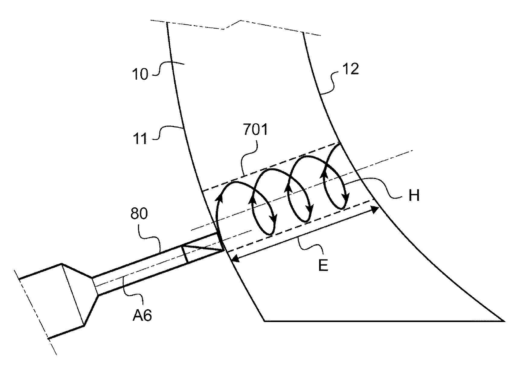
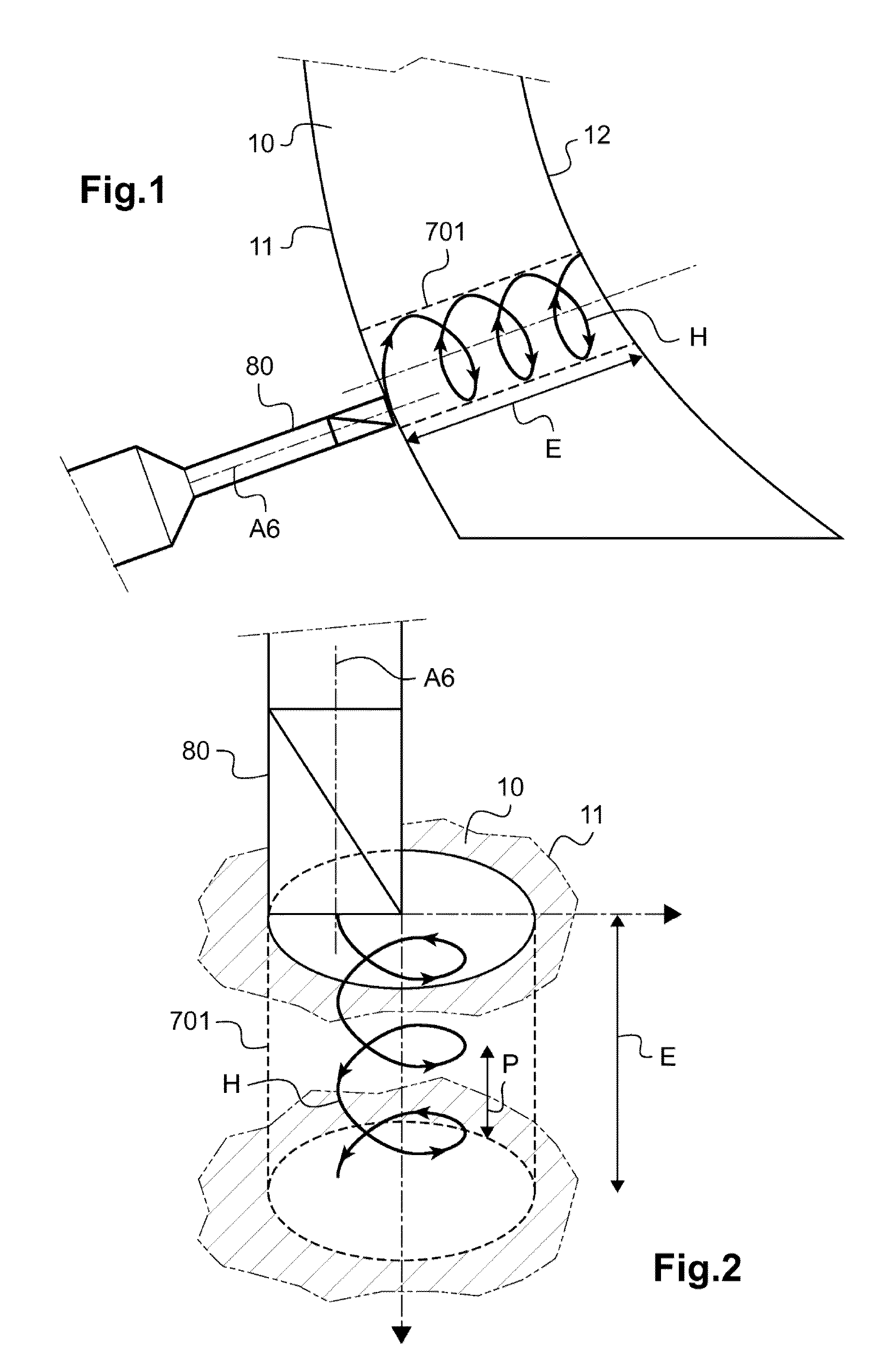
[0038]FIG. 1 is a schematic profile view of an ophthalmic lens and of a drilling tool showing the trajectory of the tip of the tool in the lens according to the drilling method according to the invention,

[0039]FIG. 2 is a schematic perspective view of the ophthalmic lens from FIG. 1, with the hole drilled by the tool and the trajectory of the tip of the tool in this lens,

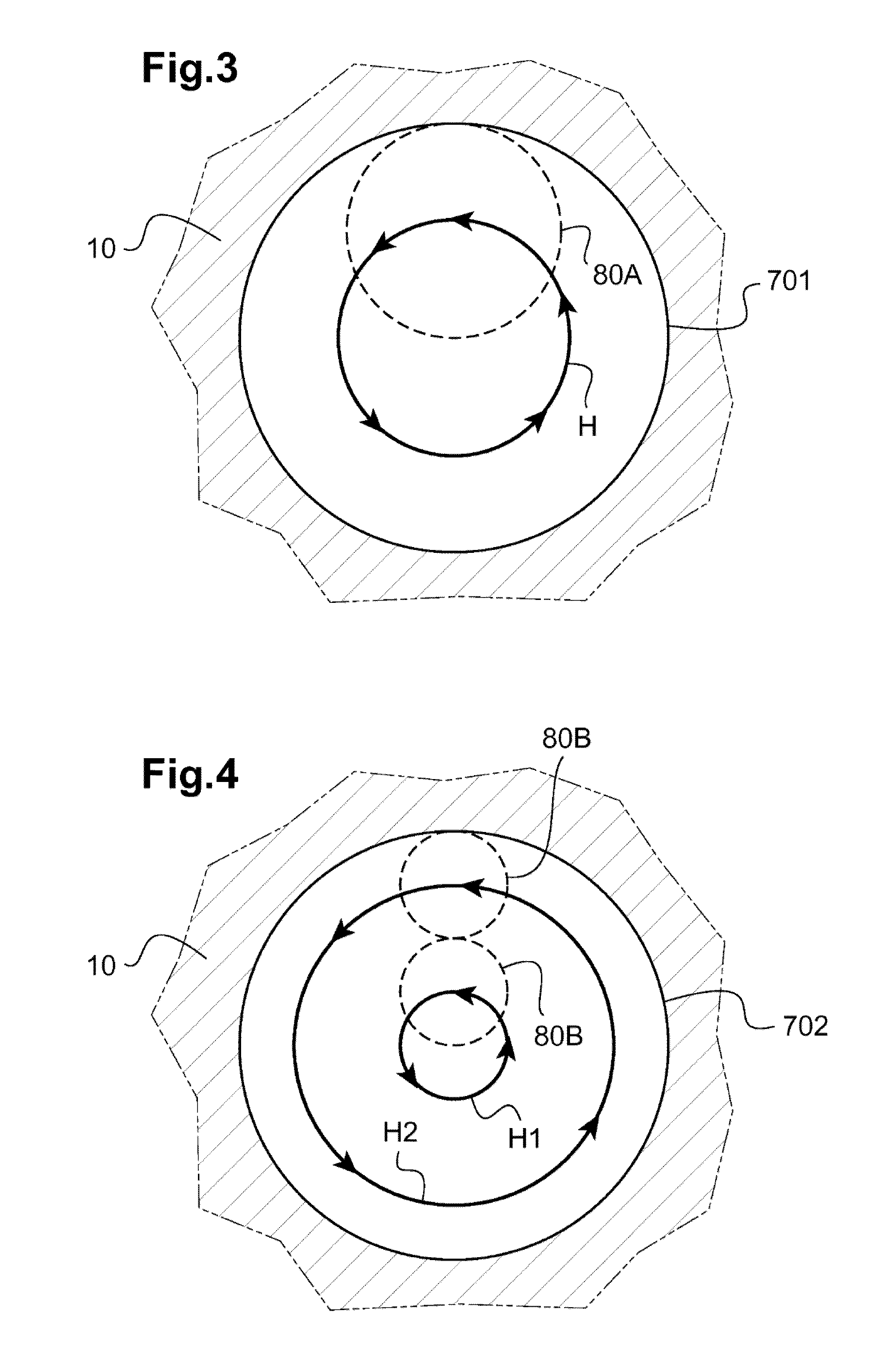
[0040]FIG. 3 is a schematic top view of the trajectory of the tip of the drilling tool from FIG. 1,

second embodiment

[0041]FIG. 4 is a schematic top view of the trajectory of the tip of the drilling tool according to the method according to the invention,

third embodiment

[0042]FIG. 5 is a schematic sectional view of an ophthalmic lens showing the trajectory of the tip of the tool in the lens according to the drilling method according to the invention,

[0043]FIG. 6 a perspective of a device for trimming and drilling an ophthalmic lens for implementing the method according to the invention,

[0044]FIG. 7 is a schematic perspective view of a drilling module of the trimming and drilling device from FIG. 6.

[0045]By way of preamble, it will be noted that identical or corresponding elements of the various embodiments shown in the figures will, as far as possible, be identified by the same reference signs and will not be described each time.

[0046]FIGS. 1 to 5 show an ophthalmic lens 10. This ophthalmic lens 10 is intended to be mounted in a frame of the “rimless” type. To this end, at least two holes 701; 702; 703 have to be drilled in each ophthalmic lens 10 in order to allow the securing of a temple and the bridge of the frame.

[0047]For this purpose, the oph...


PUM

PropertyMeasurementUnit
lengthaaaaaaaaaa
diameteraaaaaaaaaa
lengthaaaaaaaaaa

Abstract

A method for drilling an ophthalmic lens (10) includes the following steps:—memorizing the desired shape and dimensions of a drill hole (701; 702; 703) to be drilled in the ophthalmic lens (10) and the position of the opening of this drill hole on one of the faces (11, 12) of the ophthalmic lens;—positioning a drilling tool (80) facing the memorized position of the hole to be drilled;—determining a control setpoint for the transverse movement and axial advance of the drilling tool; and—drilling the ophthalmic lens according to the control setpoint. The control setpoint for the transverse movement and axial advance of the drilling tool forces the point of this drilling tool, on at least one drilling run, to follow a helical or pseudohelical trajectory depending on the desired shape and dimensions of the drill hole. An associated drilling device is also described.

Description

TECHNICAL FIELD OF THE INVENTION[0001]Generally, the present invention relates to the field of methods for drilling ophthalmic lenses.[0002]It relates more particularly to a method for drilling an ophthalmic lens, comprising the following steps of:[0003]storing the desired shape and dimensions of a drill hole in the lens and the position at which this drill hole opens onto one of the faces of the lens,[0004]positioning a drilling tool opposite the stored position of the hole to be drilled,[0005]determining a control setpoint for the transverse movement and the axial feed of the drilling tool,[0006]drilling the lens in accordance with said control setpoint.[0007]The invention also relates to an associated drilling device.PRIOR ART[0008]When the frame is of the rimless type, the trimming of the ophthalmic lens and, where applicable, the flattening of sharp edges (chamfering) are followed by the appropriate drilling of the lens so as to allow the temples and the bridge of the rimless f...

Claims


Application Information

Patent Timeline
Patent Type & Authority Applications(United States)
IPC IPC(8): B28D1/18B23C3/02G05B19/18
CPCB28D1/143B23C2220/52B23C3/02G05B2219/45129B28D1/18G05B19/182Y10T409/307616
Inventor LEMAIRE, CEDRICPINAULT, SEBASTIEN
Owner ESSILOR INT CIE GEN DOPTIQUE
Why Eureka
Try Eureka