Pneumatic tire

a technology of pneumatic tires and tires, applied in the field of pneumatic tires, can solve the problems of insufficient traction performance on snowy roads, and achieve the effect of excellent on-snow performan

Active Publication Date: 2016-05-05
SUMITOMO RUBBER IND LTD
View PDF10 Cites 18 Cited by
  • Summary
  • Abstract
  • Description
  • Claims
  • Application Information

AI Technical Summary

Benefits of technology

[0006]In view of the above problems in the conventional art, the present invention has an object to provide a pneumatic tire that may exhibit in excellent on-snow performance.

Problems solved by technology

Unfortunately, since the shoulder main groove of the pneumatic tire circumferentially extends in a straight manner, traction performance on snowy road is not sufficient.

Method used


Image

  • Pneumatic tire
  • Pneumatic tire
  • Pneumatic tire

Examples


Embodiment Construction

[0031]An embodiment of the present invention will be explained below with reference to the accompanying drawings. It should be noted that like elements are denoted by the same reference numerals throughout the disclosure.

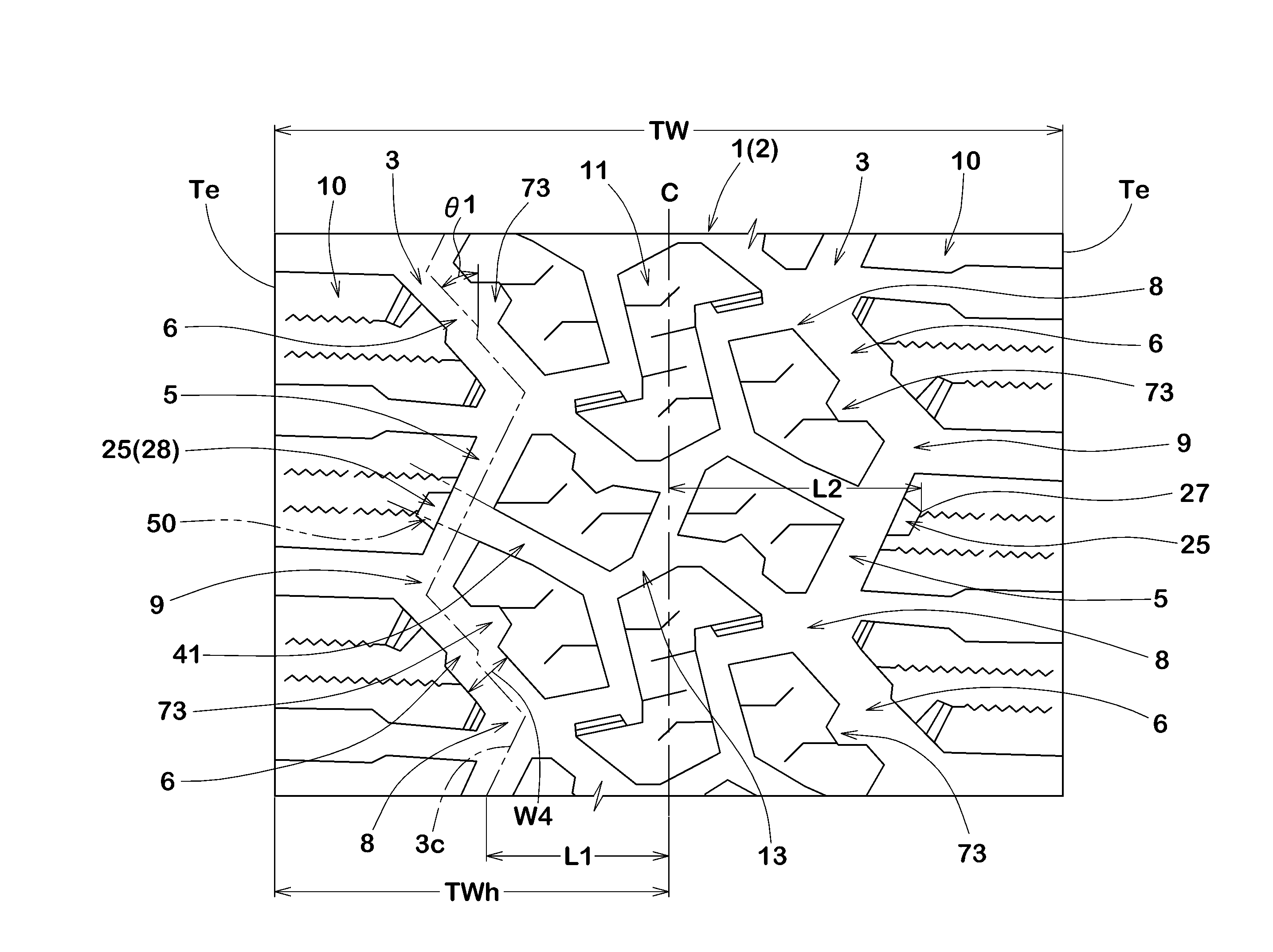
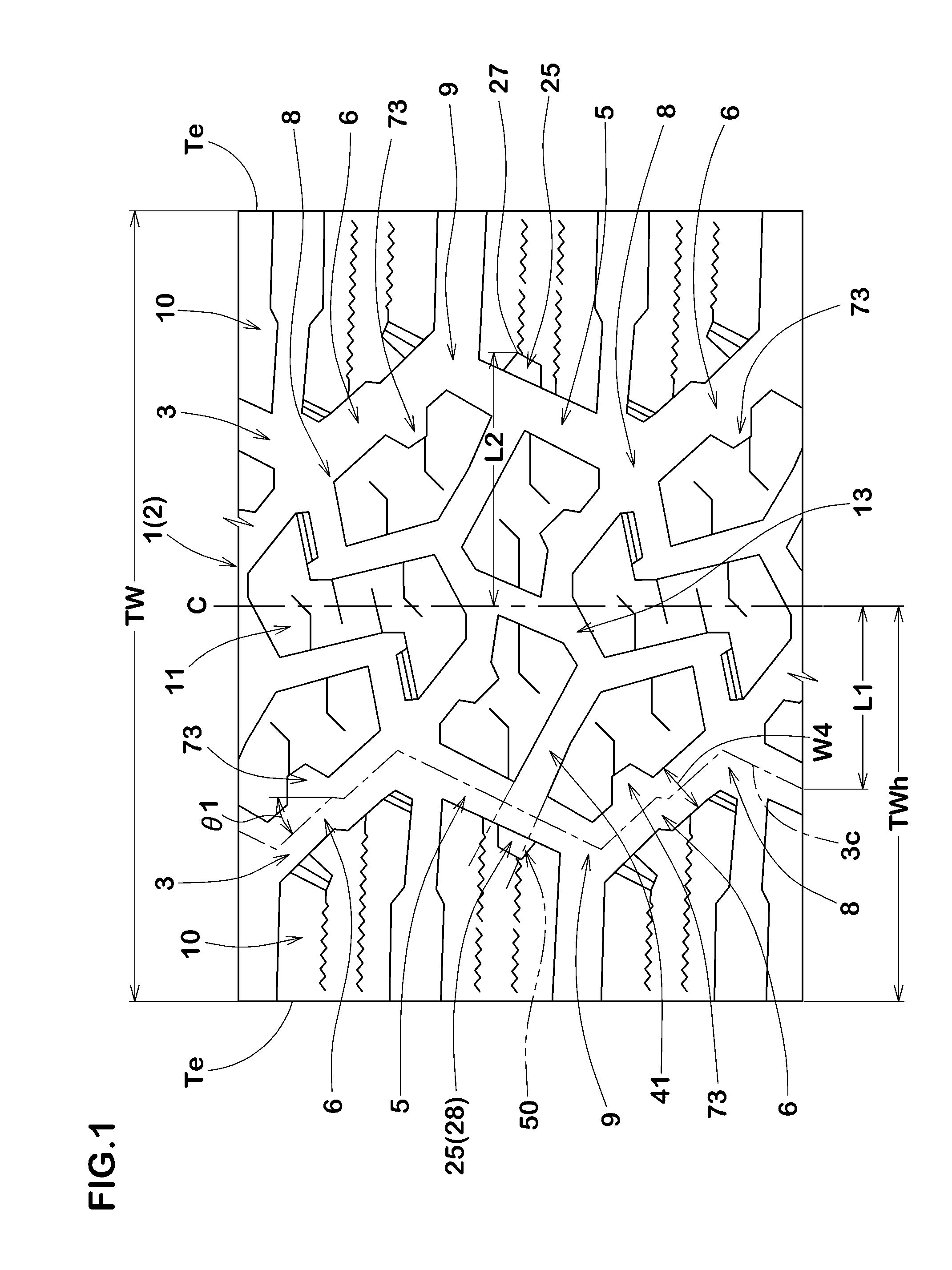
[0032]FIG. 1 illustrates a tread portion 2 of a pneumatic tire 1 in accordance with an embodiment of the present invention. The pneumatic tire 1, for example, may preferably be embodied for SUV that suitably travel on a rough terrain.

[0033]As shown in FIG. 1, the tread portion 2 of the tire 1 is provided with a pair of shoulder main grooves 3 and 3.

[0034]Each shoulder main groove 3 extends in a zigzag manner in a circumferential direction of the tire and is located adjacent to each tread edge Te.

[0035]In each side of the tire equator C, the tread edge Te refers to an axially outermost edge of the ground contacting patch of the tread portion 2 which occurs under a normally inflated loaded condition when the camber angle of the tire is zero. The normally inflated load...


PUM


Abstract

A pneumatic tire includes a tread portion provided with a circumferentially and continuously extending zigzag shoulder main groove located adjacent to a tread edge to define a shoulder portion axially outward of the shoulder main groove and a central lateral groove extending axially inwardly from the shoulder main groove. The shoulder portion includes a top surface having an axially inner edge facing the shoulder main groove and a sidewall extending radially inwardly from the inner edge. The sidewall of the shoulder portion is provided with a shoulder dent portion dented axially outwardly from the shoulder main groove. The central lateral groove is located so that an extended portion in which the central lateral groove is extended axially outwardly overlaps with the shoulder dent portion at least partially.

Description

BACKGROUND OF THE INVENTION[0001]1. Field of the Invention[0002]The present invention relates to pneumatic tires, and in particular, relates to a pneumatic tire that may exhibit in excellent on-snow performance.[0003]2. Description of the Related Art[0004]Japanese Unexamined Patent Application Publication No. 2012-201335 discloses a pneumatic tire that includes a tread portion having a shoulder main groove to define a shoulder portion between the shoulder main groove and a tread edge, wherein the shoulder portion is provided with a shoulder dent portion dented axially outwardly from the shoulder main groove. When the pneumatic tire travels on snowy road, the shoulder dent portion may compress snow which be introduced therein and then the shoulder dent portion may shear it to increase traction on snowy road.[0005]Unfortunately, since the shoulder main groove of the pneumatic tire circumferentially extends in a straight manner, traction performance on snowy road is not sufficient. Fur...

Claims


Application Information

Patent Timeline
Patent Type & Authority Applications(United States)
IPC IPC(8): B60C11/03B60C11/13
CPCB60C11/0327B60C11/1307B60C2011/0372B60C2011/0346B60C2011/0365B60C2011/133
Inventor KAGEYAMA, NAOKI
Owner SUMITOMO RUBBER IND LTD
Why Eureka
Try Eureka