Pneumatic Tire

a pneumatic tire and tire technology, applied in the field of pneumatic tires, can solve the problems of reducing difficult to achieve both steering stability on dry road surfaces and snow performance, and achieve the effect of enhancing snow performance and appropriately maintaining steering stability

Active Publication Date: 2021-07-08
THE YOKOHAMA RUBBER CO LTD
View PDF0 Cites 0 Cited by
  • Summary
  • Abstract
  • Description
  • Claims
  • Application Information

AI Technical Summary

Benefits of technology

[0005]The present technology provides a pneumatic tire that can enhance snow performance while appropriately maintaining steering stability on dry road surfaces.

Problems solved by technology

However, when an all-season tire is structured such that the groove area is increased in order to improve snow performance, steering stability on dry road surfaces may decrease, and in the aforementioned various tread structures, it is difficult to achieve both steering stability on dry road surfaces and snow performance.

Method used


Image

  • Pneumatic Tire
  • Pneumatic Tire
  • Pneumatic Tire

Examples


examples

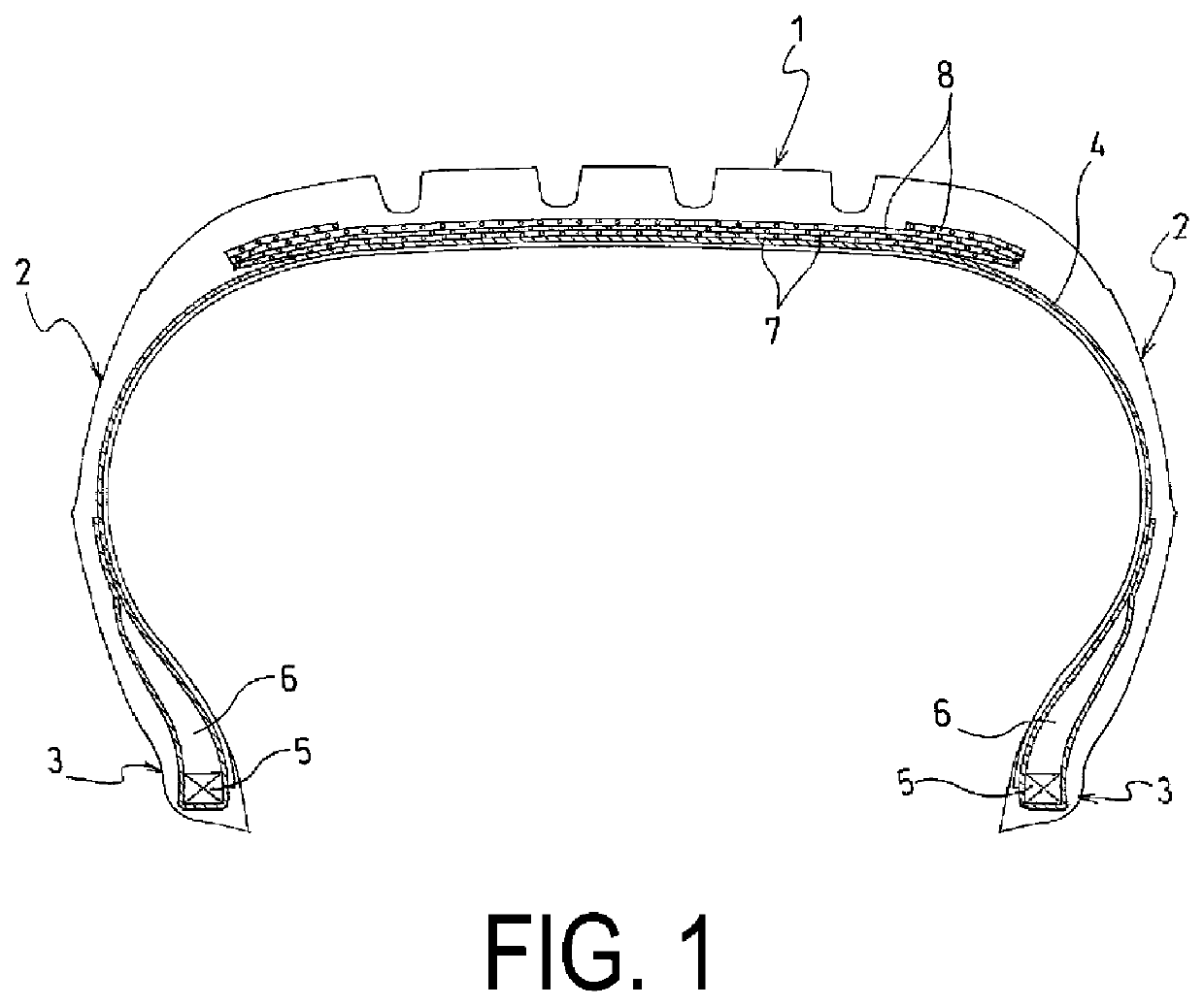
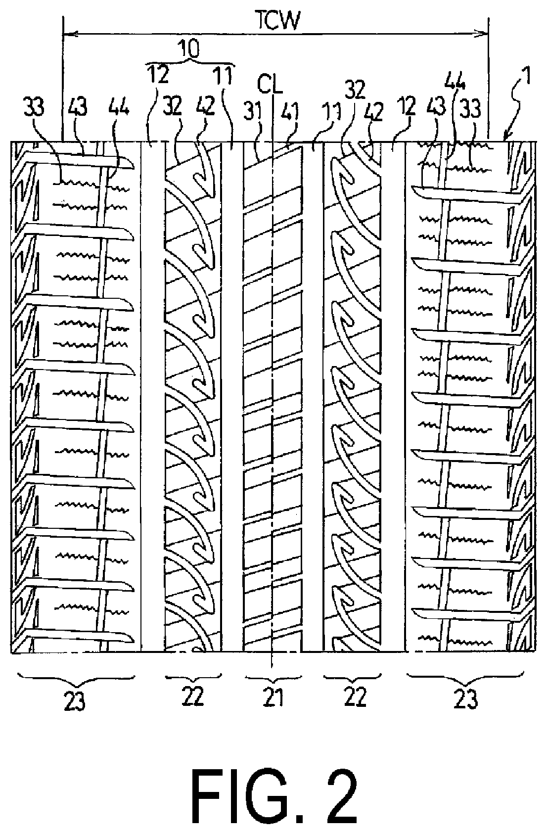
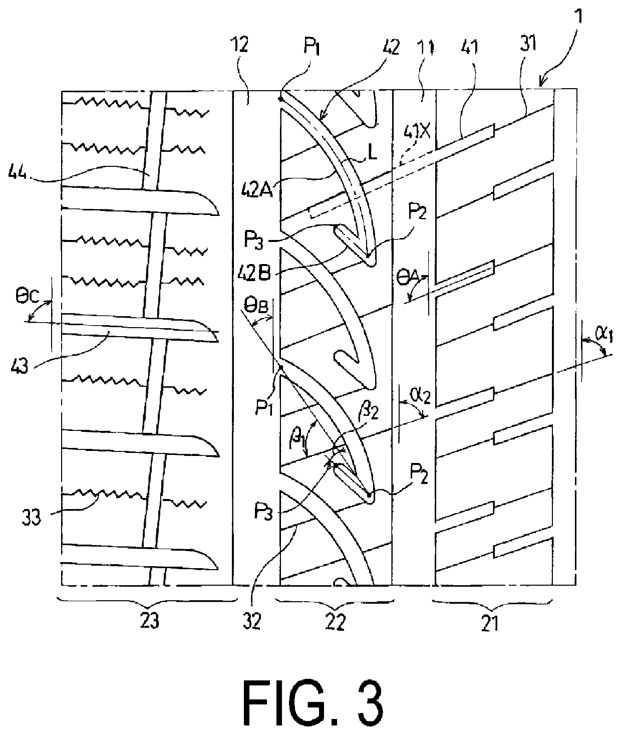
[0032]A pneumatic tire having a tire size of 205 / 55R16 91V includes: a tread portion extending in a tire circumferential direction and having an annular shape; a pair of sidewall portions disposed on both sides of the tread portion; and a pair of bead portions disposed inward of the sidewall portions in a tire radial direction. In the pneumatic tire, as illustrated in FIG. 2, a pair of first main grooves extending in the tire circumferential direction and a pair of second main grooves extending in the tire circumferential direction are formed in the tread portion. A first land portion is defined between the pair of first main grooves, and second land portions are respectively defined between one of the first main grooves and one of the second main grooves and between the other of the first main grooves and the other of the second main grooves. Third land portions are defined outward of the respective second main grooves. A plurality of first sipes (groove width: 1.0 mm) extending in...


PUM


Abstract

A tire includes a tread, sidewalls, beads, and pairs of first and second grooves formed in the tread. A first land is between the first grooves, and second lands are between one of the first and second grooves and between another of the first and second main grooves. First sipes and lateral grooves are in the first land, at the same angle, the first sipes being connected to the lateral grooves. The first sipe and the lateral groove open to one of the first grooves. Second sipes and auxiliary grooves are in a bent shape in the second land. The first and second sipes are oriented the same. The auxiliary groove includes first and second portions. An intersection angle of the first portion with the second sipe is within 45° to 90°. A length a of the first portion and a length b of the second portion satisfy 0.05×a≤b≤0.4×a.

Description

TECHNICAL FIELD[0001]The present technology relates to a pneumatic tire suitable as an all-season tire, and in particular, the present technology pertains to a pneumatic tire that can enhance snow performance while appropriately maintaining steering stability on dry road surfaces.BACKGROUND ART[0002]An all-season tire is required to exhibit excellent snow performance at the time of snowfall. Accordingly, a conventional all-season tire is designed to include a plurality of main grooves disposed in a tread portion to extend in a tire circumferential direction, and a plurality of sipes or lug grooves extending in a tire lateral direction are disposed in land portions defined by the main grooves. Thus, snow traction is ensured by the sipes or the lug grooves (for example, see Japan Unexamined Patent Publication Nos. 2009-173241 and 2009-214761).[0003]In addition, a tire structured such that a plurality of sub grooves each having a bent shape are formed in land portions of a tread portio...

Claims


Application Information

Patent Timeline
Patent Type & Authority Applications(United States)
IPC IPC(8): B60C11/12B60C11/04
CPCB60C11/1236B60C11/1204B60C2011/036B60C11/04B60C2011/1213B60C11/1272B60C2011/1209B60C2011/0381B60C2011/0372B60C2011/0365
Inventor NAGAYASU, MASAAKI
Owner THE YOKOHAMA RUBBER CO LTD
Why Eureka
Try Eureka