Pneumatic tire

a technology of pneumatic tires and tread patterns, which is applied in the direction of non-skid devices, vehicle components, transportation and packaging, etc., can solve the problems of unsuitability of tread patterns with curved diagonal grooves as described above, and achieve the effect of improving snow performance, decreasing resistance to uneven wear, and improving snow performan

Active Publication Date: 2015-05-26
THE YOKOHAMA RUBBER CO LTD
View PDF7 Cites 1 Cited by
  • Summary
  • Abstract
  • Description
  • Claims
  • Application Information

AI Technical Summary

Benefits of technology

[0008]Therefore, an object of the present invention is to provide a pneumatic tire that can improve a snow performance without decreasing resistance to uneven wear in comparison with the known pneumatic tire. With a pneumatic tire according to the present invention, a snow performance is improved without decreasing a resistance to uneven wear in comparison with the known pneumatic tire.

Problems solved by technology

A tread pattern having curved diagonal grooves as described above can be unsuitable to use as a tread pattern of an all-season pneumatic tire for a passenger car because the tread pattern is not sufficiently resistant to uneven wear and may not provide sufficient traction performance on snow and thus, may not perform sufficiently well on snow.

Method used


Image

  • Pneumatic tire
  • Pneumatic tire
  • Pneumatic tire

Examples


Embodiment Construction

[0015]Selected embodiments will now be explained with reference to the drawings. It will be apparent to those skilled in the art from this disclosure that the following descriptions of the embodiments are provided for illustration only and not for the purpose of limiting the invention as defined by the appended claims and their equivalents.

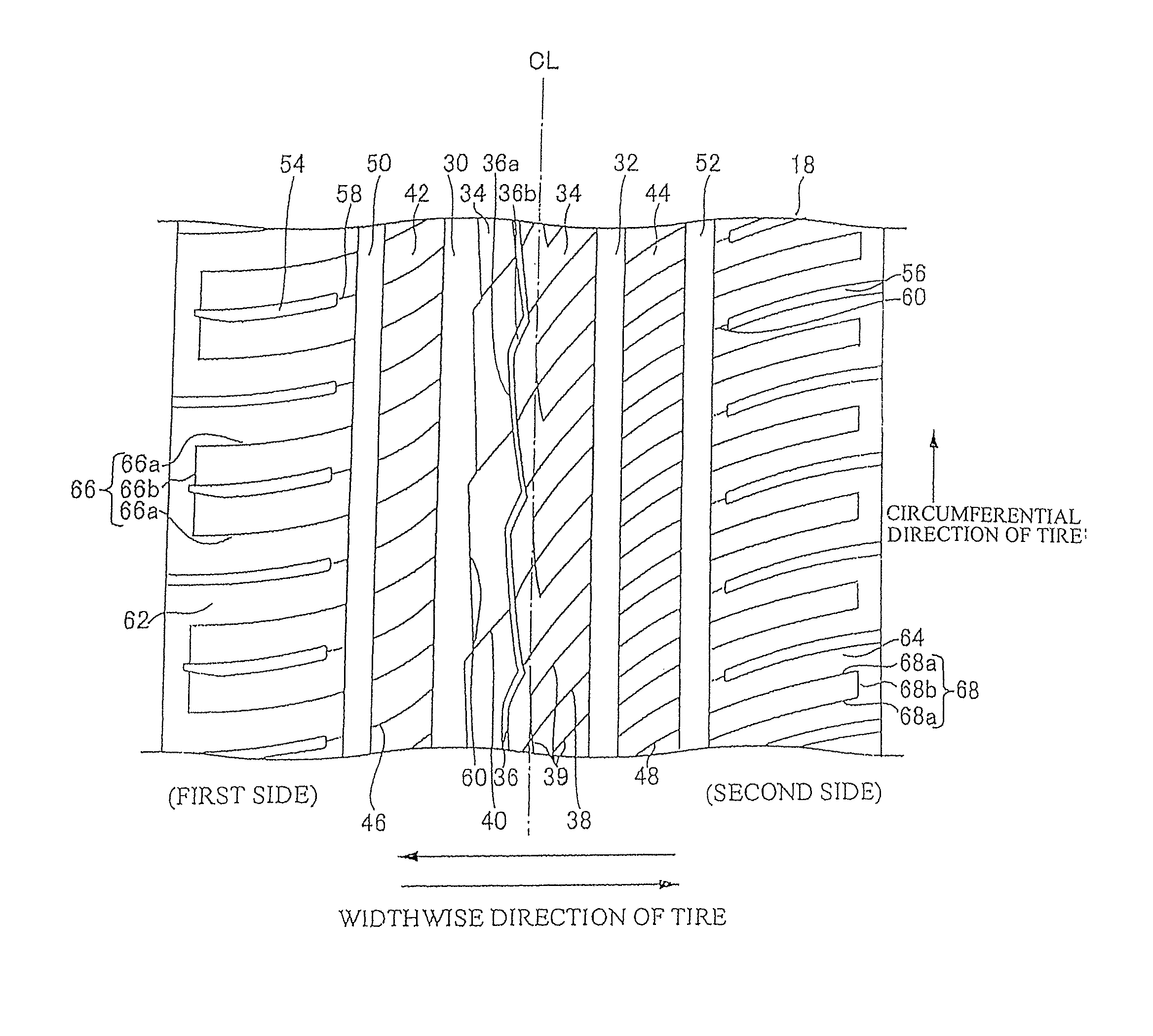
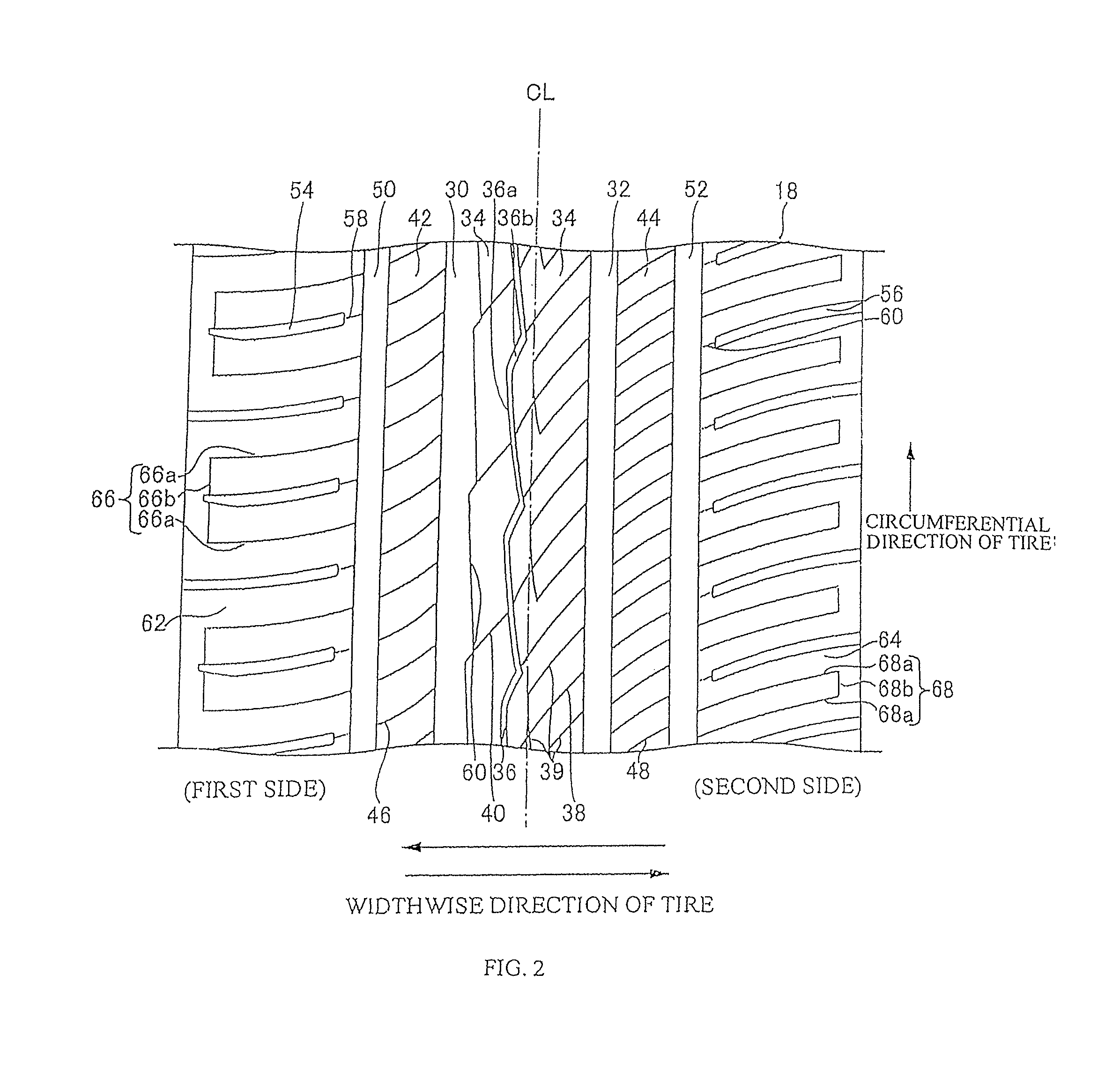
[0016]A pneumatic tire according to a disclosed embodiment will now be described. FIG. 1 is a cross sectional view of a pneumatic tire 10 (also referred to simply as a “tire”) according to an embodiment. The pneumatic tire 10 is, for example, a tire for a passenger car. A passenger car tire can be a tire defined according to Chapter A of the JATMA Yearbook 2009 (standards of The Japan Automobile Tyre Manufacturers Association, Inc.). The tire 10 can also be a small truck tire as defined in Chapter B or a truck tire or bus tire as defined in Chapter C, or a type of tire suitable with any other type of vehicle.

[0017]In the explanations that follow, ...


PUM


Abstract

A pneumatic tire includes first and second side members at first and second sides and a tread section between the first and second side members. The tread section has a tread pattern including a pair of main grooves extending linearly in a circumferential direction of the tire and a land section extending in the circumferential direction between the main grooves. The land section includes a sub groove extending in the circumferential direction without connecting to the main grooves, and a first sipe connecting between the sub groove and one of the main grooves. The sub groove includes a first groove section extending diagonally toward the first side at 0 to 30 degrees with respect to the circumferential direction and a second groove section connecting to the first groove section and extending diagonally toward the second side at 10 to 45 degrees with respect to the circumferential direction.

Description

CROSS-REFERENCE TO RELATED APPLICATIONS[0001]This application claims priority to Japanese Patent Application No. 2011-088167, filed on Apr. 12, 2011, the entire disclosure of which is hereby incorporated herein by reference.BACKGROUND[0002]1. Field of the Invention[0003]The present invention relates to a pneumatic tire having a tread pattern. More particularly, the present invention relates to a pneumatic tire having improved resistance to uneven wear and improved performance in adverse conditions, such as snow.[0004]2. Background Information[0005]An all-season pneumatic tire for a passenger car is a tire developed as an intermediate tire between a normal tire for non-snowy seasons and a snow tire (i.e., a “winter tire”), and is widely used in the United States and Europe. An all-season pneumatic tire needs to have superior resistance to uneven wear while also ensuring sufficient traction performance and resistance to lateral slipping on snow during snowfall.[0006]Japanese Laid Open...

Claims


Application Information

Patent Timeline
Patent Type & Authority Patents(United States)
IPC IPC(8): B60C11/03B60C11/12B60C11/04B60C11/13
CPCB60C11/1392B60C11/0304B60C2011/0341B60C11/1236B60C2011/0374
Inventor MATSUSHITA, KOHTARO
Owner THE YOKOHAMA RUBBER CO LTD
Why Eureka
Try Eureka