Check patentability & draft patents in minutes with Patsnap Eureka AI!

Operating parameter circuitry and method

Active Publication Date: 2016-05-05
ARM LTD
View PDF2 Cites 5 Cited by
  • Summary
  • Abstract
  • Description
  • Claims
  • Application Information

AI Technical Summary

Benefits of technology

This patent describes an operating parameter circuit that generates an operating parameter signal for functional circuitry operating from a separate power supply. The circuit includes a control loop circuit that generates the operating parameter signal based on an input signal and a replica generator circuit that also generates a further operating parameter signal based on the input signal. The two signals are then compared and an adjusted input signal is generated based on the comparison. The adjusted input signal is received by the control loop circuit to ultimately result in the functional circuitry receiving a proper operating parameter signal. The technical effect of this invention is to provide a more accurate and efficient operating parameter signal for functional circuitry.

Problems solved by technology

Problems arise, however, when noise occurs.
However, due to the variance in supply voltage, the clock signal may become distorted while being disseminated through the clock path.
When either of these things happens, the above mentioned interference of data signals may occur.
This happens because data signals may no longer be provided at the correct time.
For example, if the clock signal is too fast (due to noise) then a component may not have completed outputting a signal before the next clock pulse occurs.
This may result in components operating on the wrong data signals or multiple signals interfering with each other.
However, these approaches often introduce cycle-to-cycle jitter, which may degrade static timing margins.
In particular, if the clock signal, for example, is changed in order to compensate for a sudden change in noise, it is possible that some components will benefit whilst other components will perform more poorly.
Furthermore, since a clock signal may take time to disseminate through the clock path, it is possible that a sudden change in noise, if compensated for, will worsen the situation by the time the amended clock signal reaches the components.
In contrast, if an adjustment is applied to an operating parameter such as a clock signal for an extended period of time, the efficacy of the circuit may decrease.
For example, if the average frequency of a clock signal is decreased then the overall speed of the system will also decrease—thereby resulting in an overall less efficient data processing apparatus.

Method used


Image

  • Operating parameter circuitry and method
  • Operating parameter circuitry and method
  • Operating parameter circuitry and method

Examples


Embodiment Construction

[0017]Before discussing the embodiments with reference to the accompanying figures, the following description of embodiments and associated advantages is provided.

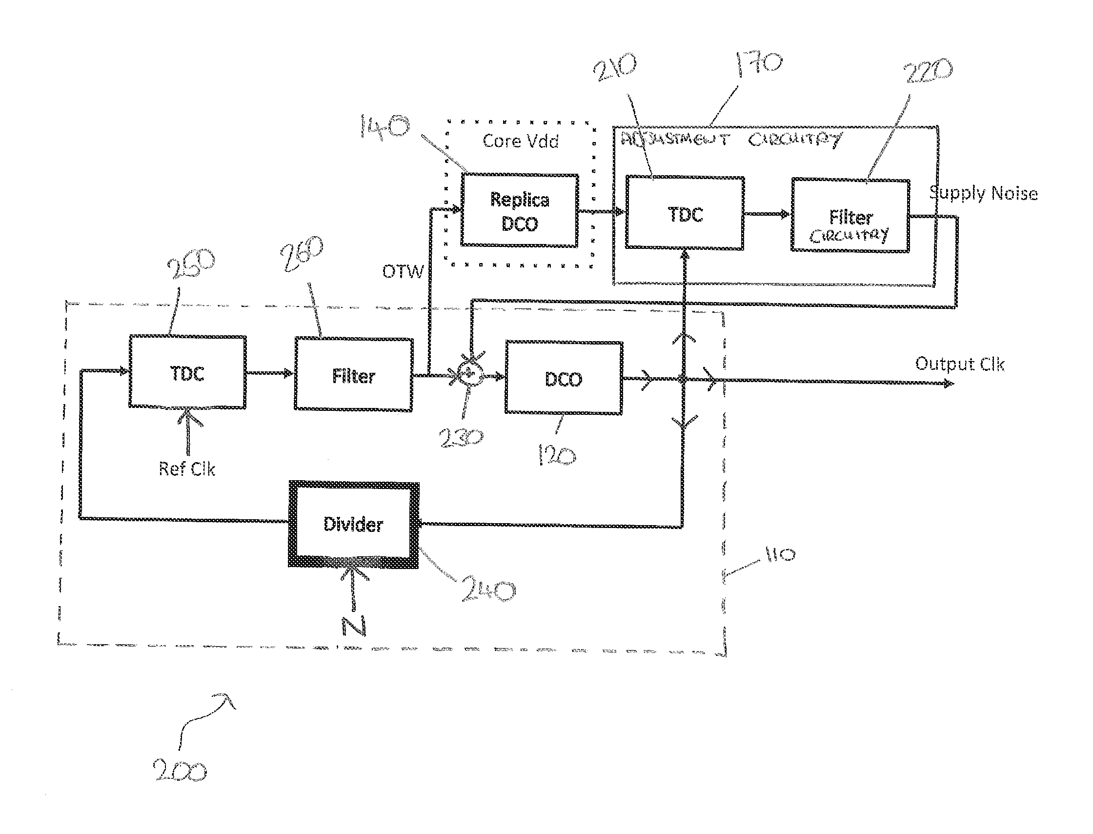
[0018]In the first aspect, control loop circuitry is provided for generating an operating parameter signal which is provided to functional circuitry. The control loop circuitry comprises generator circuitry. Replica generator circuitry is also provided, which is the same as the generator circuitry and which generates a further operating parameter signal. Whereas the generator circuitry is powered by a first power supply, the replica generator circuitry is powered by a second power supply, which is also used to power the functional circuitry. The first power supply is separate (e.g. different) from the second power supply.

[0019]Accordingly, as a result of being powered by the same power supply that powers the functional circuitry, the replica generator circuitry and the further operating parameter signal generated by the re...


PUM


Abstract

An operating parameter method and circuitry are provided that generate operating parameter signals that are compensated for noise. Such operating parameter circuitry includes control loop circuitry that operates from a first power supply to provide an operating parameter signal to functional circuitry operating from a second power supply separate from the first power supply. The control loop circuitry comprises generator circuitry to generate the operating parameter signal based on an input signal. Replica generator circuitry operates from the second power supply to generate a further operating parameter signal based on the input signal. Adjustment circuitry performs a comparison on the operating parameter signal and the further operating parameter signal and causes an adjusted input signal to be produced in dependence on a result of the comparison. The adjusted input signal is received by the generator circuitry. Consequently, the generator circuitry is able to produce an operating parameter signal that has been compensated for noise in the circuit.

Description

TECHNICAL FIELD[0001]The present disclosure relates to the field of methods and circuitry for operating parameters.DESCRIPTION OF THE PRIOR ART[0002]In a data processing apparatus, one or more components may be regulated by use of a clock signal. Those components may operate in response to, for example, a rising edge of the clock signal. By clocking components in this manner, it is possible to provide a regulated period of time in which signals can move around. This helps to ensure that operations performed by circuitry are performed in “lockstep”, i.e. as a component outputs a data signal, another input signal will arrive at that component to be processed at the next rising clock edge. Keeping components in lockstep can help to prevent data signals from interfering with each other.[0003]Problems arise, however, when noise occurs. For example, when components in the functional circuitry operate, they draw current. This causes the supply voltage to vary. In other words, the operation...

Claims


Application Information

Patent Timeline
IPC IPC(8): H03L7/08G04F10/00
CPCG04F10/005H03L7/08H03L7/102H03L7/0992H03L2207/06
Inventor WHATMOUGH, PAUL NICHOLASBULL, DAVID MICHAEL
Owner ARM LTD
Features
  • R&D
  • Intellectual Property
  • Life Sciences
  • Materials
  • Tech Scout
  • Unparalleled Data Quality
  • Higher Quality Content
  • 60% Fewer Hallucinations
Learn More