Airborne Geophysical Survey System

Active Publication Date: 2016-05-12
PORTERFIELD ISAAC MAX
View PDF2 Cites 7 Cited by
  • Summary
  • Abstract
  • Description
  • Claims
  • Application Information

AI Technical Summary

Benefits of technology

[0016]An objective of the present invention is to provide a multi-rotor drone as the support platform for an airborne EM system. A series of substantially horizontal, inner and outer polygonal, aluminum tubes comprise part of the structural frame of the drone. These tubes serve as the multi-turn, set of EM transmitting coils giving the overall transmitting coil assembly a very large geometric area. The invention may further provide a set of three, orthogonal, receiver sensor coils suspended with shock-absorbing cables beneath the aircraft. The receiver sensor coil

Problems solved by technology

The response to movement and vibration of receiver sensors in all EM systems is a significant source of noise.
Airborne systems are se

Method used


Image

  • Airborne Geophysical Survey System
  • Airborne Geophysical Survey System
  • Airborne Geophysical Survey System

Examples


Embodiment Construction

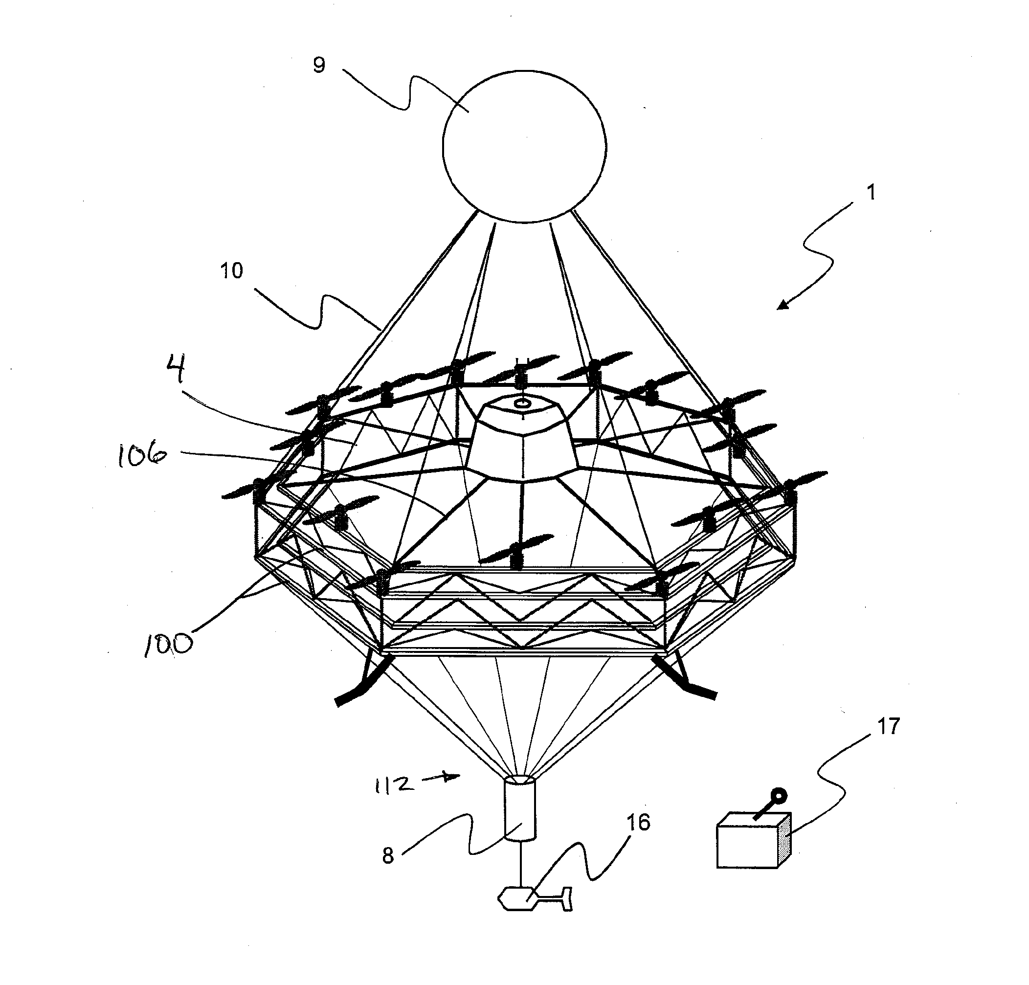
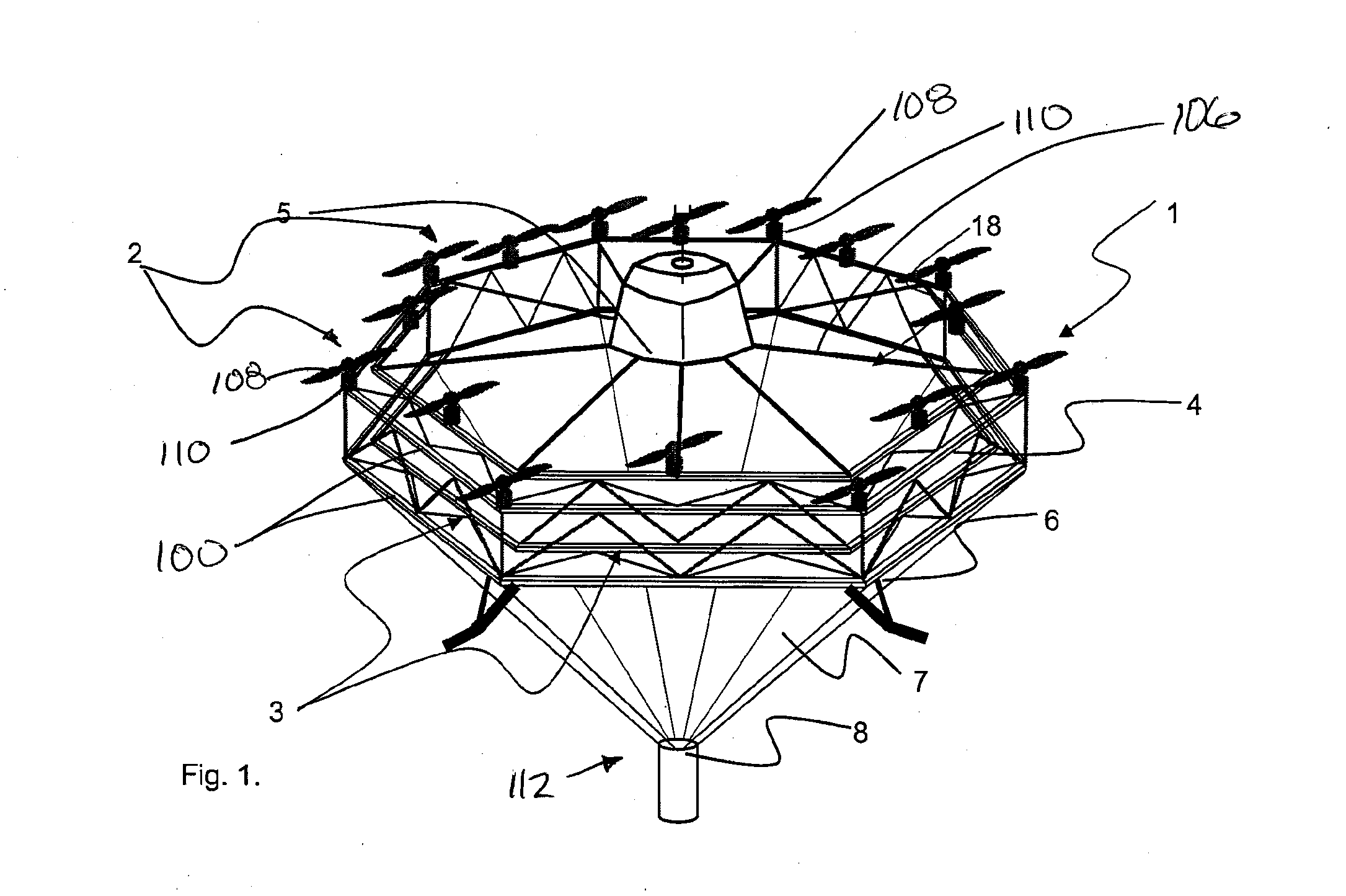
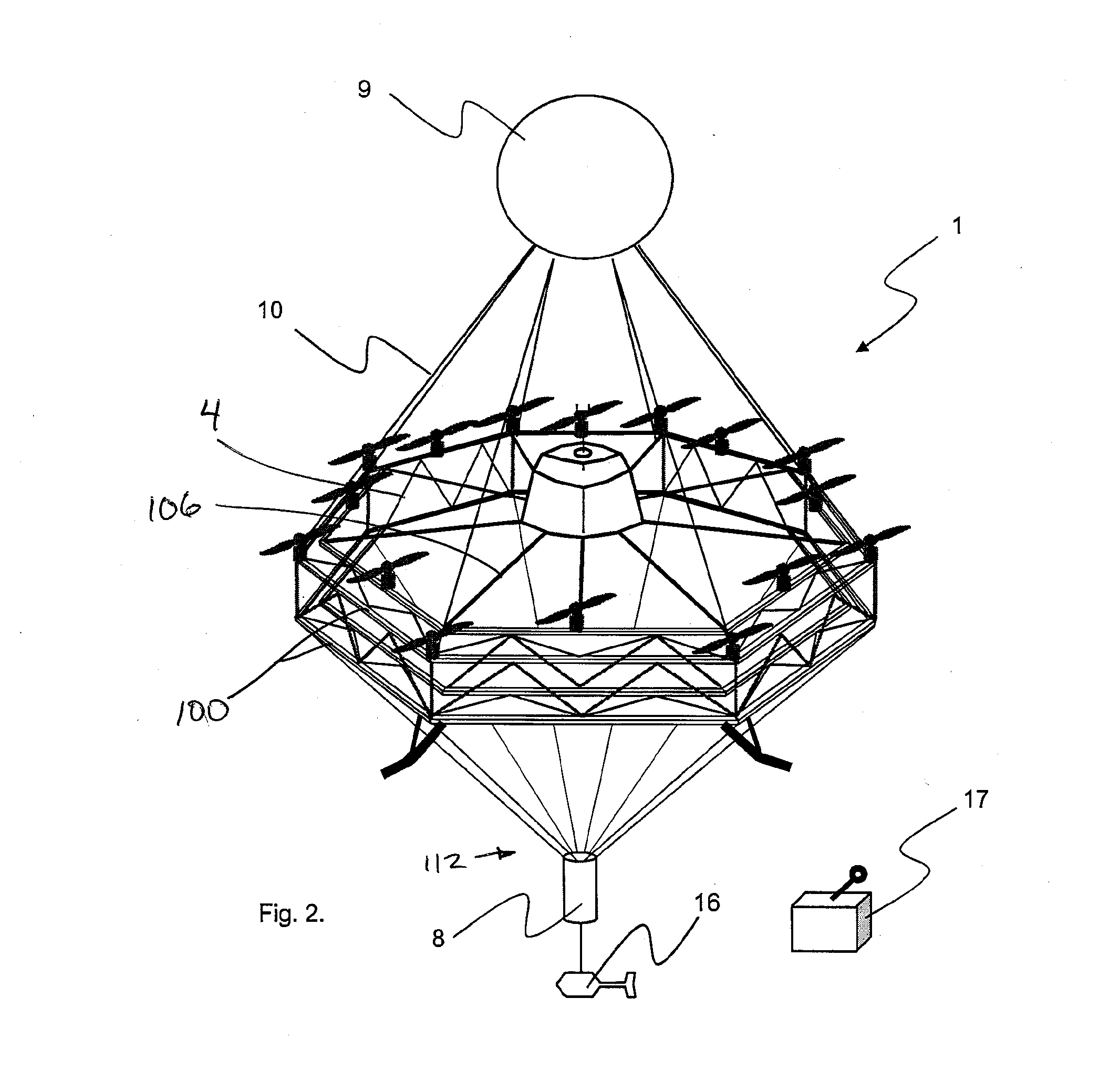
[0054]The present invention comprises an airborne (frequency or time domain) EM survey system 1. The survey system 1 includes a multi-rotor, drone 18, a series of transmitting coils 3, transmitter and receiver assembly in an onboard console 5, an EM receiver sensor 8 and a magnetometer sensor 16. FIG. 1 is a perspective view of the apparatus of the present invention in the airborne, operational mode. In this embodiment the high density receiver sensor 8 is suspended centrally beneath the drone 18 by means of cables 7 attached, equidistantly from the outer, lower edge of the drone frame 3, thereby creating a pendulum effect for stability of the aircraft during flight.

[0055]The survey system 1 is propelled and maneuvered by increasing or decreasing the speed of the rotors 2 independently. This maneuvering is accomplished by means of flight software algorithms. The drone 18 is an unmanned air vehicle (UAV) with flight path being managed on the ground from a remote control unit 17.

[0056...


PUM


Abstract

An airborne ElectroMagnetic (EM) survey system wherein the system includes; first, a series of transmitter coils, which induce a primary (EM) field into the earth resulting in a secondary EM field being created in any sub-surface electrically conductive bodies; and second, a set of three orthogonal receiver coils which detect the secondary EM field. Multiple transmitter coils through which an electric current is pumped, form part of the structural, aluminum framework of a multi-rotor drone. The receiver sensor may be an EM induction sensor, comprised of multi-turn, copper windings, mounted inside an aerodynamic bird and separated by non-conductive sphalerite, which acts as an electrical insulator to limit self-induction and capacitance.
Additionally a lighter-than-air balloon may be used to add vertical lift and increase a pendulum effect.

Description

FIELD OF THE INVENTION[0001]This invention relates in general to the field of airborne geological mapping and more specifically relates to a method and apparatus for conducting geophysical surveys, which transmit and receive electromagnetic (EM) fields for the detection of conductive material in the earth and claims the benefit under 35 U.S.C.119(e) of U.S. provisional application Ser. No. 62 / 075,674, filed Nov. 5, 2014.BACKGROUND[0002]Electromagnetic (EM) geophysical techniques induce electrical currents in the earth using electromagnetic induction. A time varying magnetic field is created using a coil or loop of wire on or above the earth's surface. Faraday's law of induction tells us that a changing magnetic field will produce an electric field, which in turn will create an electric current. Thus, the primary magnetic field from the transmitter loop will create a secondary electric current in the earth. Finally, we measure the secondary magnetic field produced by those secondary ...

Claims


Application Information

Patent Timeline
IPC IPC(8): G01V3/16G01V3/17
CPCG01V3/17G01V3/16G01V3/165
Inventor VOWLES, ALAN
Owner PORTERFIELD ISAAC MAX
Why Eureka
Try Eureka