Eureka AIR delivers breakthrough ideas for toughest innovation challenges, trusted by R&D personnel around the world.

Heat transferring arrangement

a technology of heat transfer arrangement and heat transfer element, which is applied in the direction of lighting and heating apparatus, semiconductor devices for light sources, and support devices for lighting and heating. it can solve the problems of long operation life of leds, and inability to provide sufficient cooling for standalone heat sinks. it can improve the thermal conductivity between the centre portion and the heat transfer element, and reduce the friction coefficien

Active Publication Date: 2014-12-18
SIGNIFY HLDG BV
View PDF16 Cites 7 Cited by
  • Summary
  • Abstract
  • Description
  • Claims
  • Application Information

AI Technical Summary

Benefits of technology

The present invention provides a heat transferring arrangement for LED lights that can transfer heat generated by the LEDs to the housing, reducing the need for an external fan or membrane to manage cooling. The arrangement includes elongated heat transferring elements that can bend and adjust to the specific geometry of the housing. The second end portions of the elements form a geometric area that is larger than the cross-sectional area of the housing, allowing for a better thermal connection between the elements and the housing. This results in improved heat transfer and reduced interchangeability issues with traditional lighting technology. The elongated elements can be connected to the centre portion of the housing or formed on a generally circular or rectangular centre portion, depending on the specific housing. The technical effect of this invention is to provide a more efficient and effective heat transfer solution for LED lights.

Problems solved by technology

Furthermore, LEDs have a long operational lifetime.
Especially, when LEDs are mounted in, for example, roofs or ceilings it may become complicated to provide sufficient cooling due to the reduced surrounding space of the LEDs.
In such cases, a plurality of LEDs are placed together in a small area which provides such an amount of heat that a standalone heat sink may not be able to provide sufficient cooling.
However, these types of solutions are expensive and sometimes unreliable due to their limited operational lifetime.

Method used


Image

  • Heat transferring arrangement
  • Heat transferring arrangement
  • Heat transferring arrangement

Examples


Embodiment Construction

[0035]The present invention will now be described more fully hereinafter with reference to the accompanying drawings, in which currently preferred embodiments of the invention are shown. This invention may, however, be embodied in many different forms and should not be construed as limited to the embodiments set forth herein; rather, these embodiments are provided for thoroughness and completeness, and fully convey the scope of the invention to the skilled addressee. Like reference characters refer to like elements throughout.

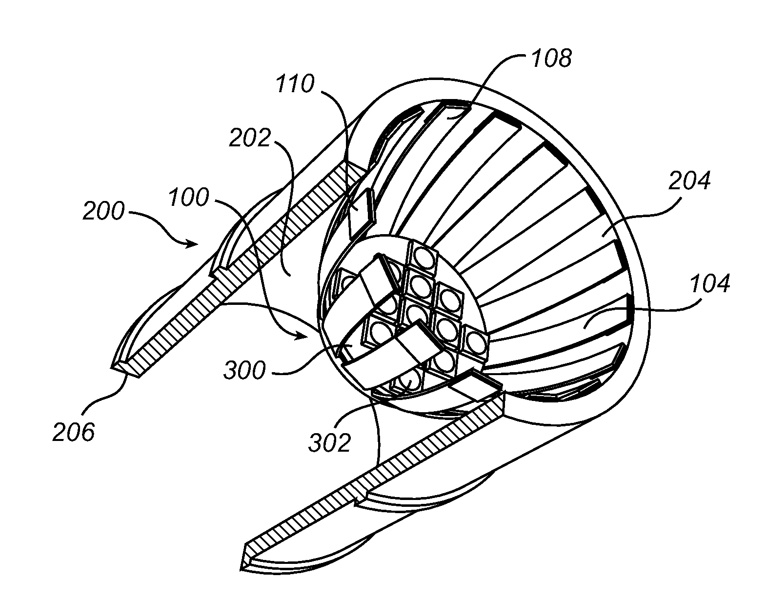
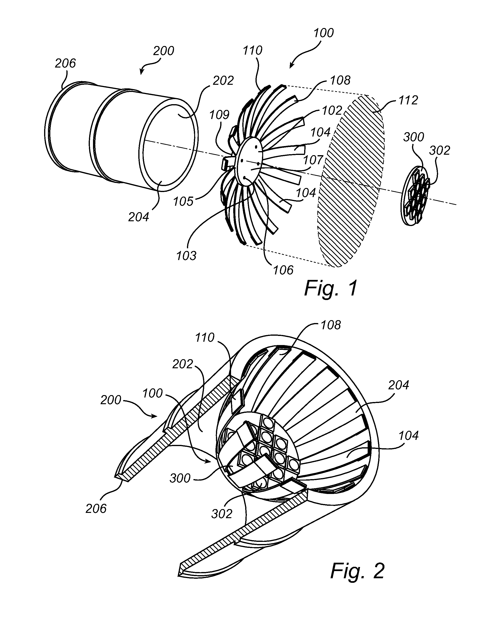
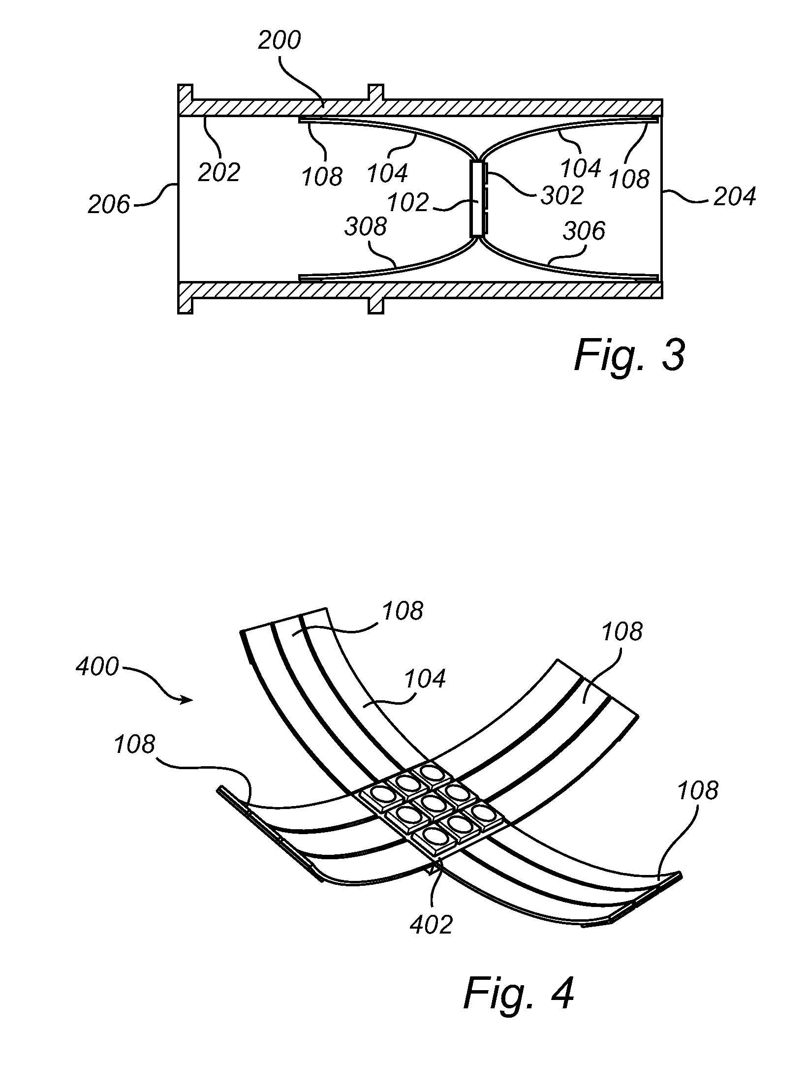
[0036]Referring now to the drawings and to FIG. 1 in particular, there is depicted a perspective view of the heat transferring arrangement 100 prior to being inserted in a housing 200 according to a currently preferred embodiment of the invention. As is illustrated in FIG. 1, the heat transferring arrangement 100 comprises a centre portion 102. The centre portion 102 is configured for mounting a LED 302 or a LED module 300, in the illustrated embodiment the LED...


PUM

PropertyMeasurementUnit
heataaaaaaaaaa
friction coefficientaaaaaaaaaa
geometric areaaaaaaaaaaa

Abstract

The present invention relates to a heat transferring arrangement (100, 400) for cooling at least one light emitting diode (302), wherein the heat transferring arrangement (100, 400) comprises a centre portion (102, 402) configured for mounting the light emitting diode (302) and adapted to receive heat generated from the light emitting diode (302) when emitting light, and a plurality of elongated heat transferring elements (104), each having a first end portion (106) connected to the centre portion (102, 402) and a second end portion (108) which when inserted in a housing (200) is configured to be in abutment with an inner surface (202) of the housing (200), so that the generated heat is thermally transferred to the housing (200). Advantages with the invention in dudes, at least, that a passive heat transferring arrangement is provided which may reduce the need of an external fan or membranes to provide sufficient cooling.

Description

TECHNICAL FIELD[0001]The present invention relates to the field of heat management of light emitting diodes, and more specifically to a heat transferring arrangement for cooling a light emitting diode. The present invention also relates to a lighting assembly comprising the above heat transferring arrangement.BACKGROUND OF THE INVENTION[0002]Light emitting diodes, LEDs, are employed in a wide range of lighting applications. As LEDs have the advantage of providing a bright light, being reasonably inexpensive and has low power consumption, it is becoming increasingly attractive to use LEDs as an alternative to traditional lighting. Furthermore, LEDs have a long operational lifetime. As an example, LED lamps may last 50 000 hours which is up to 50 times the operational life of an incandescent lamp.[0003]To achieve such a long operational lifetime, one important aspect to consider is the heat management of the LEDs so in order to avoid overheating of the LEDs or the LED module. This is ...

Claims


Application Information

Patent Timeline
Patent Type & Authority Applications(United States)
IPC IPC(8): F21V29/00F21V15/01F28F21/06F21K99/00F28F9/007F28F21/02F21V29/505
CPCF21V29/004F28F9/007F28F21/02F28F21/06F21K9/1355F21V15/011F21K9/50F21V29/2206F21Y2101/02F21V19/003F21V29/505F21V29/74F21Y2115/10F21K9/23F21V29/00F21V29/503
Inventor DEN BOER, REINIER IMRE ANTONBERNAL, JUAN DAVIDLEE, KWAN NAIGIELEN, VINCENT STEFAN DAVIDKESER, MERIJN
Owner SIGNIFY HLDG BV
Why Eureka
Eureka Blog
Learn More