Terminal shield with integrated current transformer

Active Publication Date: 2016-05-26
SCHNEIDER ELECTRIC USA INC
View PDF1 Cites 2 Cited by
  • Summary
  • Abstract
  • Description
  • Claims
  • Application Information

AI Technical Summary

Benefits of technology

[0010]The terminal shield with the integrated current transformer sensor enables standardization of load current sensing capab

Problems solved by technology

Although the terminals may be mounted slightly below the surface of the circuit breaker's casing, it is possible that an operator could be severely burned or shocked if the operator accidentally touched the terminals while installing the circuit breaker.
Further, adjacent circuit breakers could be short circuited if they were accidentally joined by a conducting material across the respective terminals.
The terminals may also be su

Method used


Image

  • Terminal shield with integrated current transformer
  • Terminal shield with integrated current transformer
  • Terminal shield with integrated current transformer

Examples


Embodiment Construction

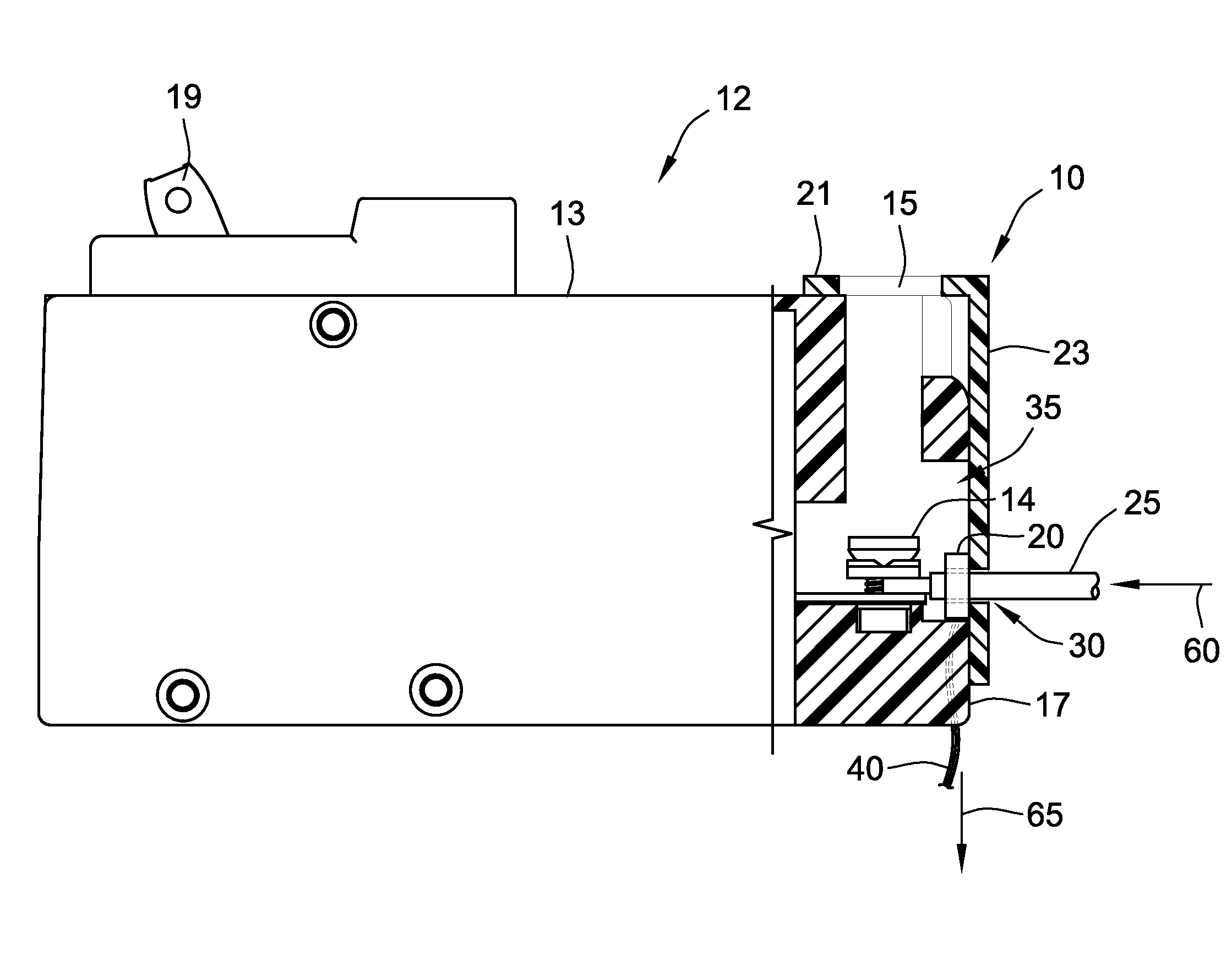
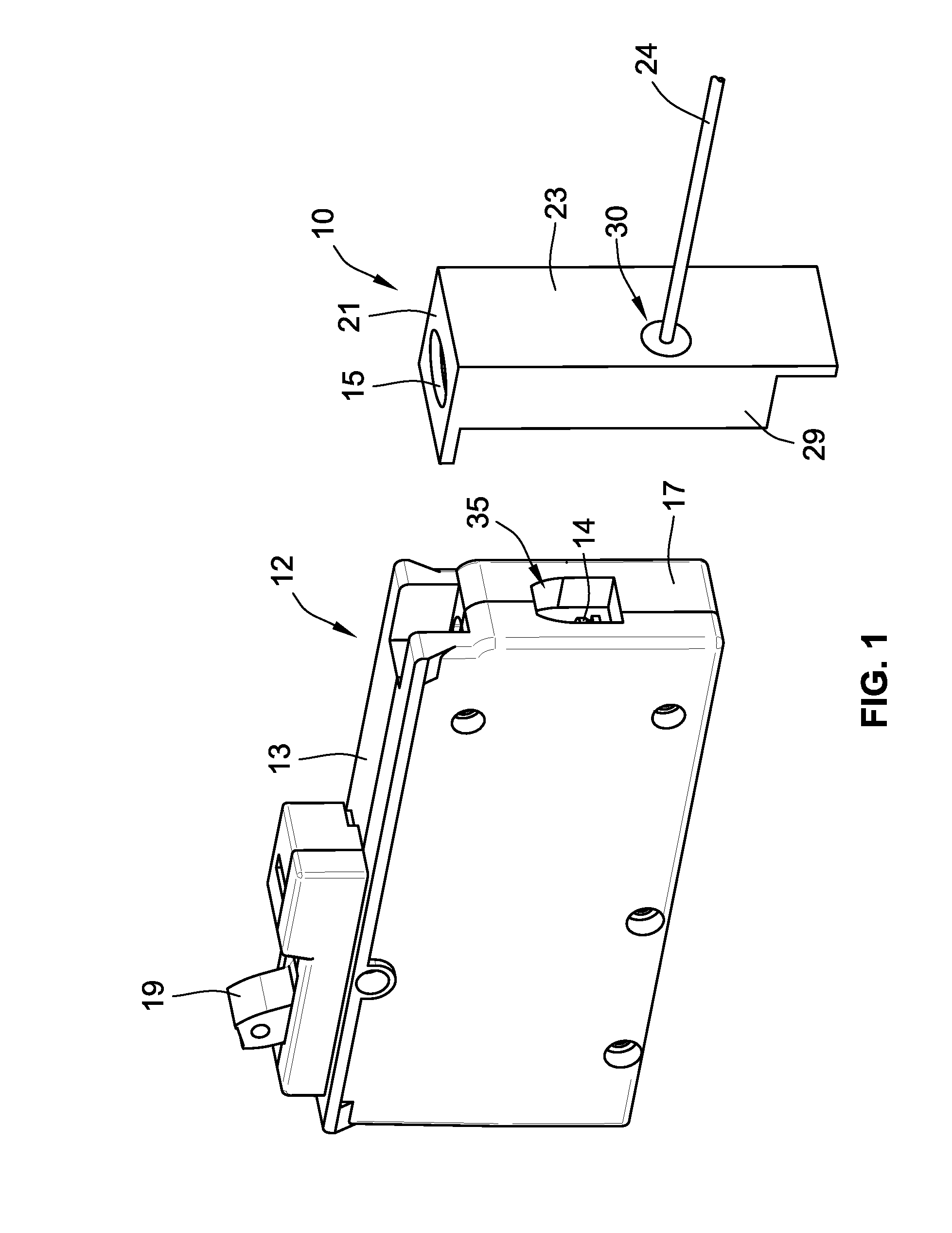
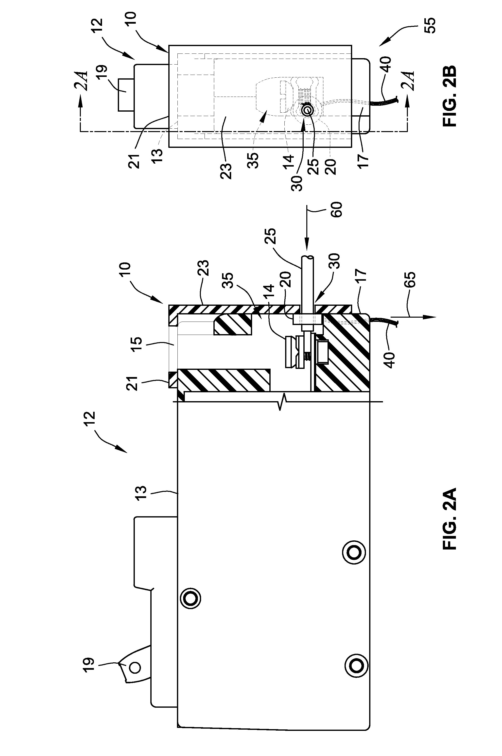
[0019]FIG. 1 is a perspective view of the an example embodiment of the invention, illustrating a single pole circuit breaker 12 and an electrically insulated terminal shield 10 for the circuit breaker 12, which is integrated with a toroidally shaped current transformer sensor 20 shown in FIG. 2A. The switch handle 19 is shown on the front face 13 of the circuit breaker 12, to enable manually connecting or disconnecting the power supply line from the load terminal 14 located within the cavity 35 on the bottom side 17 of the circuit breaker 12. The terminal shield 10 is depicted in the figure as separated from the circuit breaker so as to show the bottom side 17, the load terminal 14, and the cavity 35 of the circuit breaker 12. The terminal shield 10 comprises a shield structure including a front portion 21 that fits on the front face 13 of the circuit breaker 12 and a bottom portion 23 that fits on the bottom side 17 of the circuit breaker 10, when the terminal shield 10 is in a clo...


PUM


Abstract

A terminal shield for a circuit breaker, formed of an electrically insulating material, protects an operator from inadvertently touching the load terminal that would otherwise be exposed on the bottom side of the circuit breaker: In accordance with an example embodiment of the invention, the terminal shield is integrated with a toroidally shaped current transformer sensor, to enable measuring the current in a load wire that has been inserted through an aperture in the terminal shield. Preferably there is an access hole in the front portion of the terminal shield, which allows the operator to insert a tool through the front face of the circuit breaker, to tighten the load terminal onto the load wire. The terminal shield with the integrated current transformer sensor enables standardization of load current sensing capability for circuit breakers and further enables ease of installation without clutter in the confined regions of the load center.

Description

FIELD OF THE INVENTION[0001]The invention is generally directed to an electrically insulated terminal shield for a circuit breaker, which is integrated with a current transformer sensor.BACKGROUND OF THE INVENTION[0002]Electric circuit breakers are commonly used to protect load or branch circuits in residential and commercial buildings against electrical overload and fault conditions. Example circuit breakers comprise a pair of separable contacts, a spring-operated mechanism for causing separation of the contacts, and a tripping mechanism that automatically releases the operating mechanism to break the connection between the contacts upon the occurrence of an electrical overload or fault condition.[0003]Circuit breakers may be constructed with terminals to form an electrical connection with a load wire. Although the terminals may be mounted slightly below the surface of the circuit breaker's casing, it is possible that an operator could be severely burned or shocked if the operator ...

Claims


Application Information

Patent Timeline
IPC IPC(8): H01H9/02H01F38/20
CPCH01F38/20H01H9/0264H01F38/28H01H71/125
Inventor PARRA, JENAROKOEHRMANN, JORGEPARRA, ENRIQUE
Owner SCHNEIDER ELECTRIC USA INC
Why Eureka
Try Eureka