Carrier Body for Sanitary Surface Material

Active Publication Date: 2017-10-05
SCHINDLER MARTIN
View PDF5 Cites 2 Cited by
  • Summary
  • Abstract
  • Description
  • Claims
  • Application Information

AI Technical Summary

Benefits of technology

[0039]The carrier body, as aforesaid, can be brought into exact conformation with field dimensions during installation of the shower. Mounting and shower component alignments are aided if the drain pan bottom of the carrier body be provided with a field corrected rim periphery. To accomplish this correction, and thus ease the installation, in embodiments of the disclosed carrier body assembly the bearing surface of the carrier body has been provided with predetermined linear indentations. In this way, it is possible to make vertical cuts along the carrier body edge in the second (outer) area, guided by these indentations. By means of these guided cuttings, the premounting operation is considerably facilitated.
[0040]In a possible embodiment of the disclosed carrier body assembly, the sealing membrane is permanently bonded on first (inner) portion of the carrier body. In the remaining part of the carrier body surface, the sealing membrane loosely overlaps the carrier body surface on the second (outer) portion, which portion can now be custom cut to the dimensioning of the shower enclosure. A conforming fit can be made by means of cutting the carrier body vertically in the second (outer) portion, which, at this point of installation, is loosely overlapped by the said sealing membrane. Prior to the mentioned trimming by cutting, the loosely overlapping, sealing membrane is folded back to clear the second (outer) portion, which lies thereunder. Since the sealing membrane is now securely anchored adhesively against

Problems solved by technology

But if the carrier body cannot fit, or does not closely fit, into the prepared adjacent floor or wall structure, difficulties can arise in the sealing of the carrier body with the sealing strips, as well as difficulties applying the sanitary surface material—in particular where tiles and limiting dimensions are concerned.
A continuous sheet of solid waterproof material could be used to form the waterproof membrane but folds or creases in the sheet necessary to conform the sheet to the base prematurely stress the sheet and damages the integrity of the sheet.
The shell alone d

Method used


Image

  • Carrier Body for Sanitary Surface Material
  • Carrier Body for Sanitary Surface Material
  • Carrier Body for Sanitary Surface Material

Examples


Embodiment Construction

[0048]The following is an explanation and a more detailed description of embodiments of the disclosed carrier body assembly, with the aid of the above Figures, in accord with surrounding construction and, where necessary, also providing the method of installation and operation of the disclosed carrier body assembly.
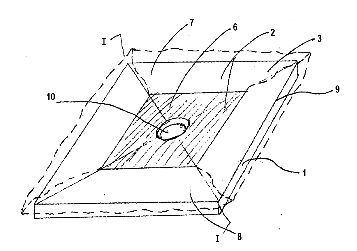
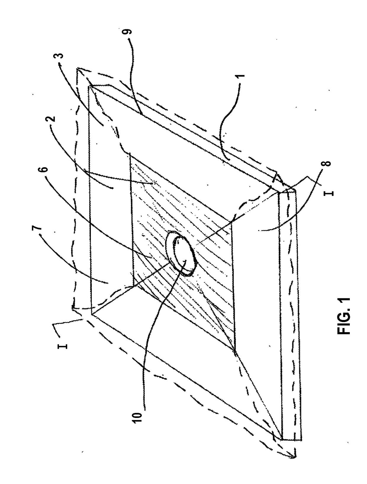
[0049]FIG. 1

[0050]In the perspective presentation of FIG. 1 of a first embodiment carrier body assembly, a carrier body 1 is depicted from an inclined view from above. In this view, the carrier body 1 possesses an upward exposed bearing surface 2, which is to be provided with a sanitary surfacing material 3. This surfacing material may be an acrylic coating or a tile covering or the like. In the perspective view of FIG. 1 the basic bearing surface 2 is designated as having within its borders an inner, centrally located “first” partial area 6. Correspondingly, the surface 2 also possesses a peripherally surrounding outer “second” partial area 7. The said first (inner) part...


PUM


Abstract

A carrier body assembly for forming part or all of a shower floor includes a rigid carrier body having a bearing surface for sanitary surface material such as tile and a sealing membrane that overlies the top or bottom surface of the carrier body but is attached to only a portion of the top or bottom surface. The unattached portion of the membrane is folded away from the carrier body to enable trimming of the carrier body to fit without damaging the membrane. After installation of the carrier body the membrane overlies the adjacent shower structure to form a watertight, water-impermeable connection between the carrier body and the adjacent shower structure.

Description

RELATED APPLICATIONS[0001]This application claims priority from applicant's co-pending U.S. patent application Ser. No. 12 / 682,625 “ Carrier Body for Sanitary Surface Material, Method of Adapting Such a Carrier Body to Floor Dimensions of a Sanitary Shower Facility, and Use of the Carrier Body” filed 20 Apr. 2010 at Attorney Docket No. 7-4261, which in turn is a US nationalization of now expired PCT Patent Application No. PCT / EP2008 / 008872 filed 20 Oct. 2008, which PCT application claims priority from German Patent Application DE 2007050150.3-16 filed 19 Oct. 2007, which priority applications are each incorporated by reference as if fully set forth herein.FIELD OF THE DISCLOSURE[0002]The disclosure relates to a carrier body for sanitary surface material such as tiles, acrylic coatings, or the like found in shower facilities.BACKGROUND OF THE DISCLOSURE[0003]Where shower facilities are involved, a carrier body is provided that is protected by a sanitary surface material such as tile ...

Claims


Application Information

Patent Timeline
IPC IPC(8): A47K3/40A47K3/16
CPCA47K3/40A47K3/1605
Inventor SCHINDLER, MARTIN
Owner SCHINDLER MARTIN
Why Eureka
Try Eureka