Fuel filter monitor

Inactive Publication Date: 2009-01-29
ELWOOD ROBERT M
View PDF11 Cites 3 Cited by
  • Summary
  • Abstract
  • Description
  • Claims
  • Application Information

AI Technical Summary

Benefits of technology

[0009]The significance of monitoring differential pressure using a solid state sensor as opposed to a mechanical differential vacuum gauge is the ea

Problems solved by technology

Fuel filters clog over a period of time from accumulation of particles filtered from the fuel.
A clogged fuel filter degrades engine performance, and when the filter becomes sufficiently clogged, the engine will fail to op

Method used


Image

  • Fuel filter monitor
  • Fuel filter monitor
  • Fuel filter monitor

Examples


Example

[0013]Similar reference characters denote corresponding features consistently throughout the attached drawings.

DETAILED DESCRIPTION OF THE PREFERRED EMBODIMENTS

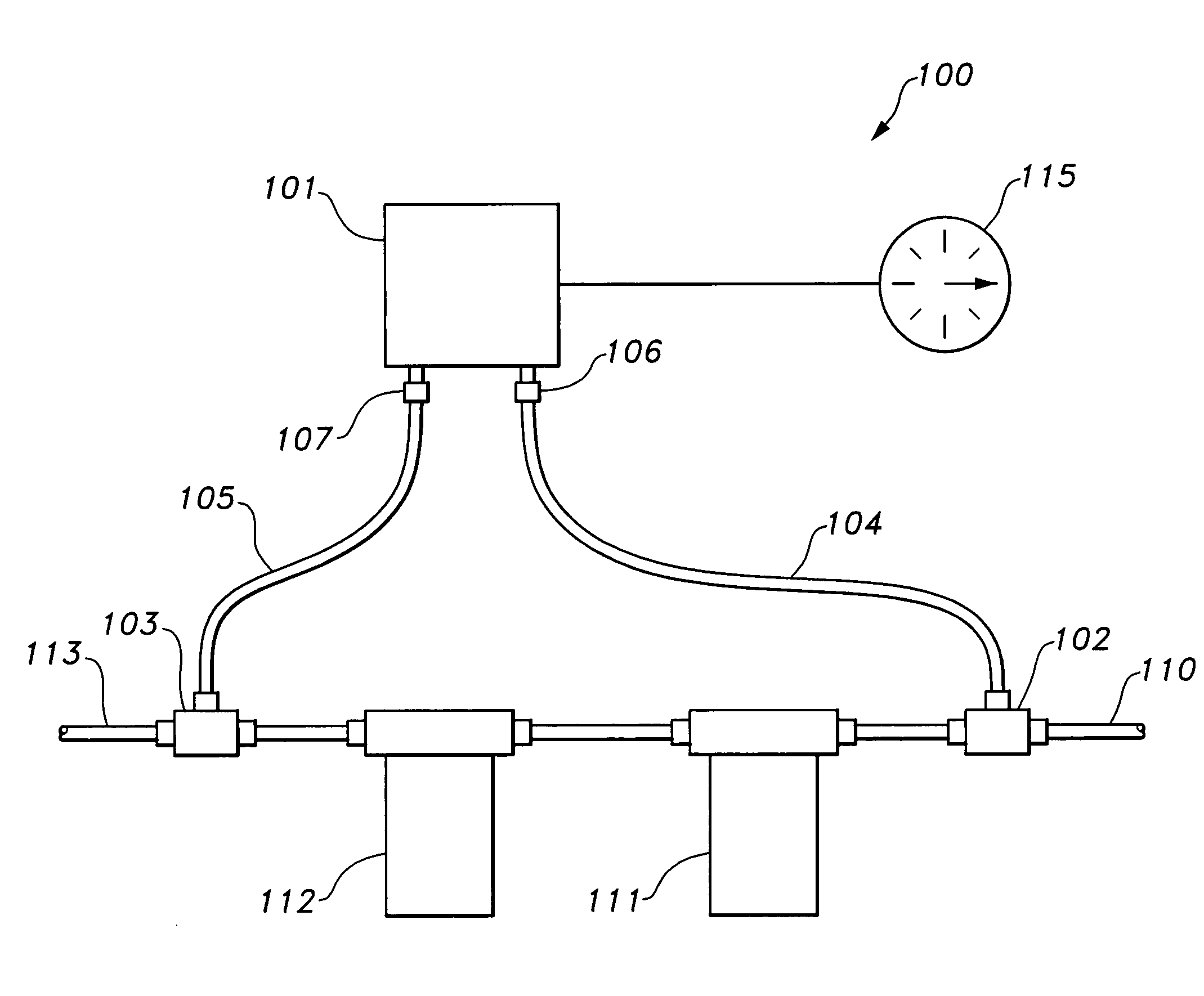
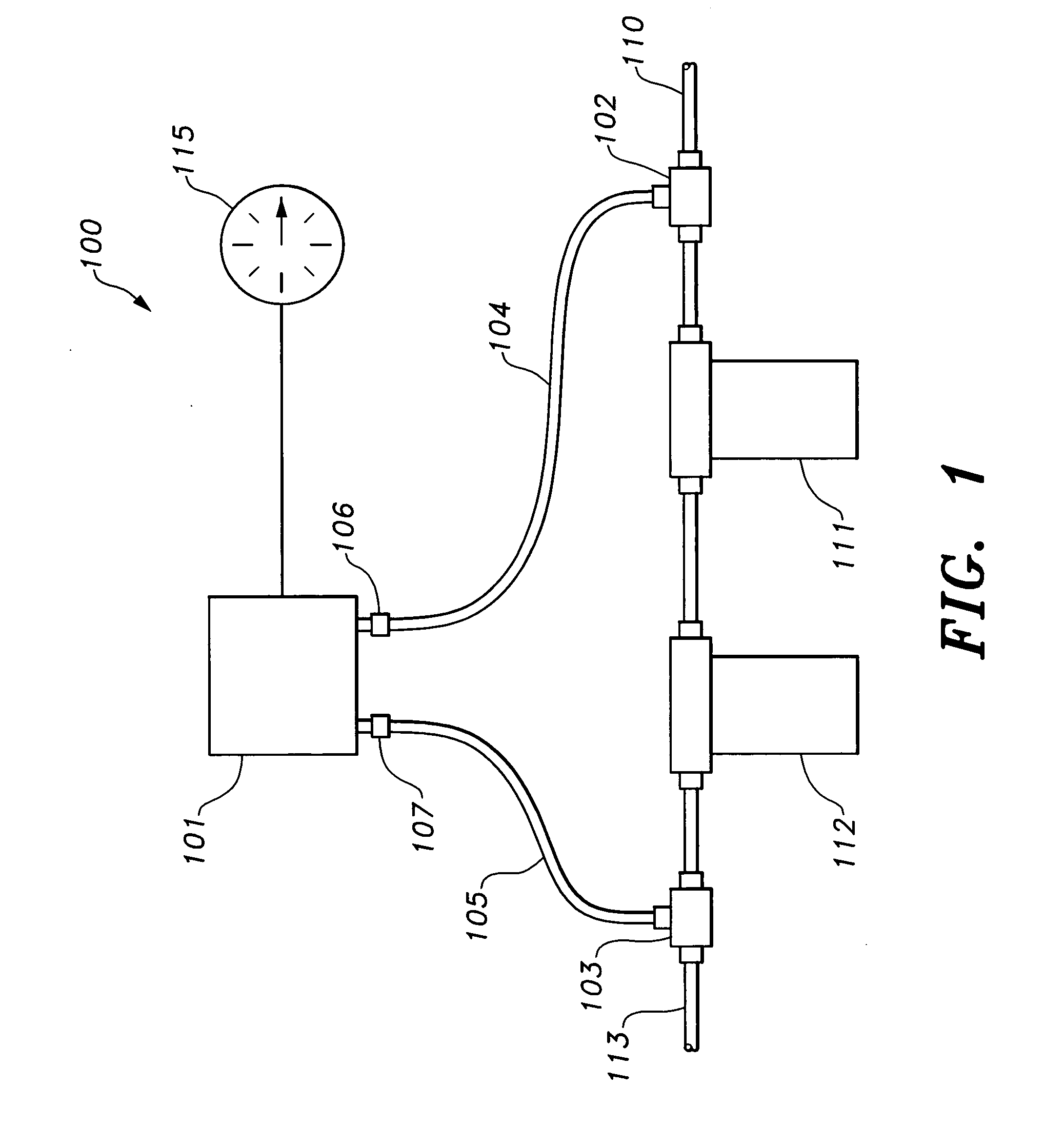
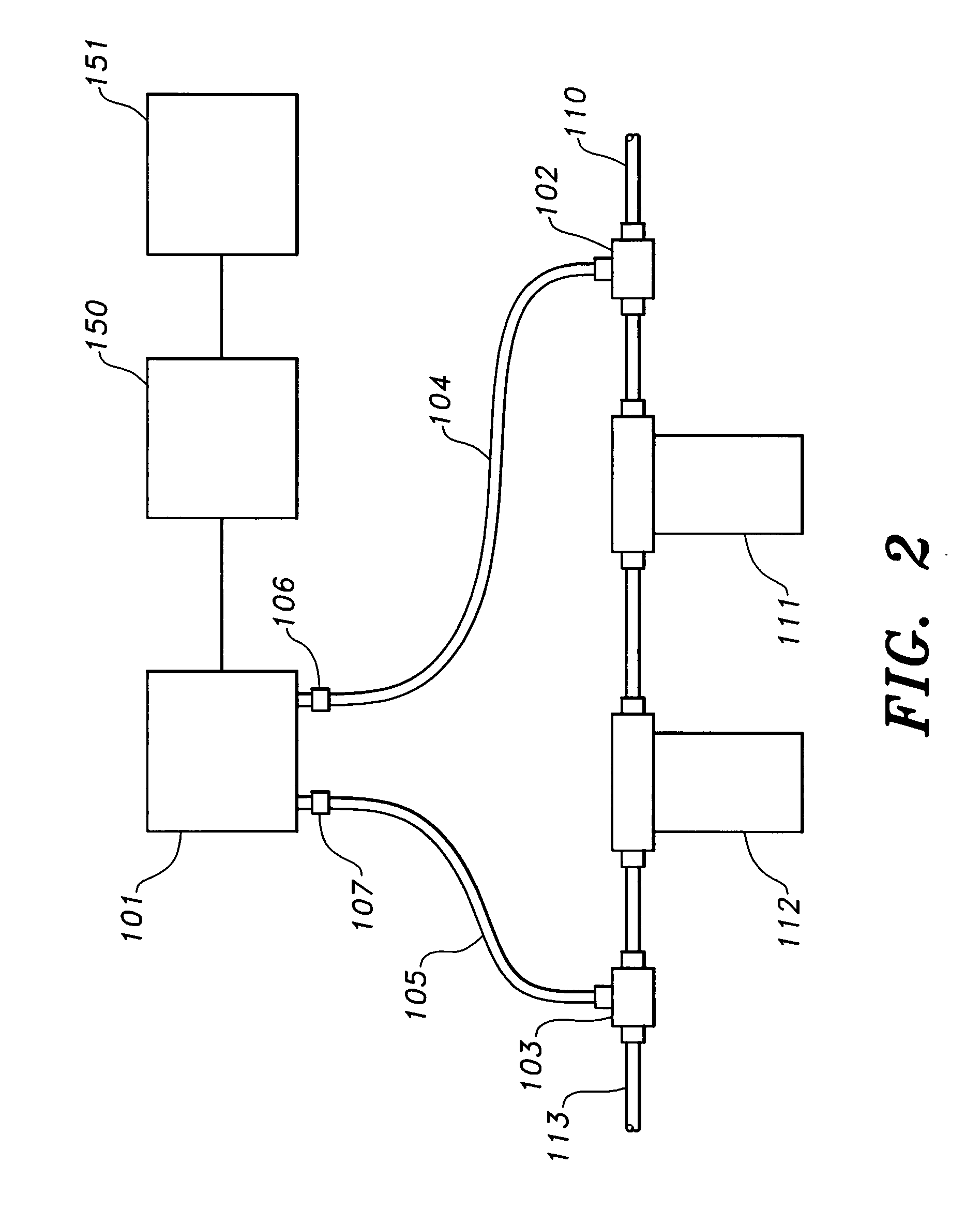
[0014]The present invention relates to a diesel fuel filter condition monitor 100. As shown in FIG. 1, a fuel line tee with valve and quick connect fitting assembly 102 is connected to the upstream portion 110 of the fuel line. Another fuel line tee with valve and quick connect fitting assembly 103 is connected to the fuel line 113 downstream from the filters 111 and 112. A first vacuum hose 104 is connected to the assembly 102 at one end and connected to high vacuum port 106 of differential pressure sensor 101 at the other end. Differential pressure sensor 101 may be a solid state piezoresistive silicon type or any other type of differential pressure sensor that provides an output that can be translated into differential pressure readings (analog or digital). Exemplary differential pressure sensors types (without limitation)...


PUM

PropertyMeasurementUnit
Pressureaaaaaaaaaa

Abstract

The fuel filter monitor measures pressure upstream and downstream of a fuel filter or filter bank. A solid state differential pressure sensor senses the pressure difference across the filter or filter bank. The analog output of the pressure sensor is connected to an electronic gauge for continuous monitoring of the pressure differential to determine if the filter is reaching clogged condition. The analog output signal can be supplied to an analog to digital converter and the digital information supplied to a processor for pressure trending.

Description

CROSS-REFERENCE TO RELATED APPLICATION[0001]This application claims the benefit of U.S. Provisional Patent Application Ser. No. 60 / 935,018, filed Jul. 23, 2007.BACKGROUND OF THE INVENTION[0002]1. Field of the Invention[0003]The present invention relates to filter monitoring apparatus. More particularly, the present invention relates to a fuel filter monitor for monitoring the differential pressure across a fuel filter or a fuel filter bank in a diesel engine.[0004]2. Description of the Related Art[0005]Diesel engines, such as engines used in boats and trucks, use fuel filters to ensure that fuel reaching the combustion chambers from the fuel tanks is clean. Fuel filters clog over a period of time from accumulation of particles filtered from the fuel. A clogged fuel filter degrades engine performance, and when the filter becomes sufficiently clogged, the engine will fail to operate. It is desirable to change fuel filters before the filter prevents operation of the engine, and to keep...

Claims


Application Information

Patent Timeline
IPC IPC(8): G08B21/00F02M37/32
CPCB01D35/143B01D37/046F02M37/22F02D33/003F02B3/06F02M37/32
Inventor ELWOOD, ROBERT M.
Owner ELWOOD ROBERT M
Why Eureka
Try Eureka