Anti-theft and anti-tipping device for electronic displays

Inactive Publication Date: 2008-08-14
J G EDELEN
View PDF25 Cites 3 Cited by
  • Summary
  • Abstract
  • Description
  • Claims
  • Application Information

AI Technical Summary

Benefits of technology

[0011]In each embodiment, the support member is preferably integral formed, in contrast to being formed of separate elements joined together such as by way of pivoting connections or the lik

Problems solved by technology

While the above described prior art attempts may have had marginal success in securing televisions or other electronic display d

Method used


Image

  • Anti-theft and anti-tipping device for electronic displays
  • Anti-theft and anti-tipping device for electronic displays
  • Anti-theft and anti-tipping device for electronic displays

Examples


Embodiment Construction

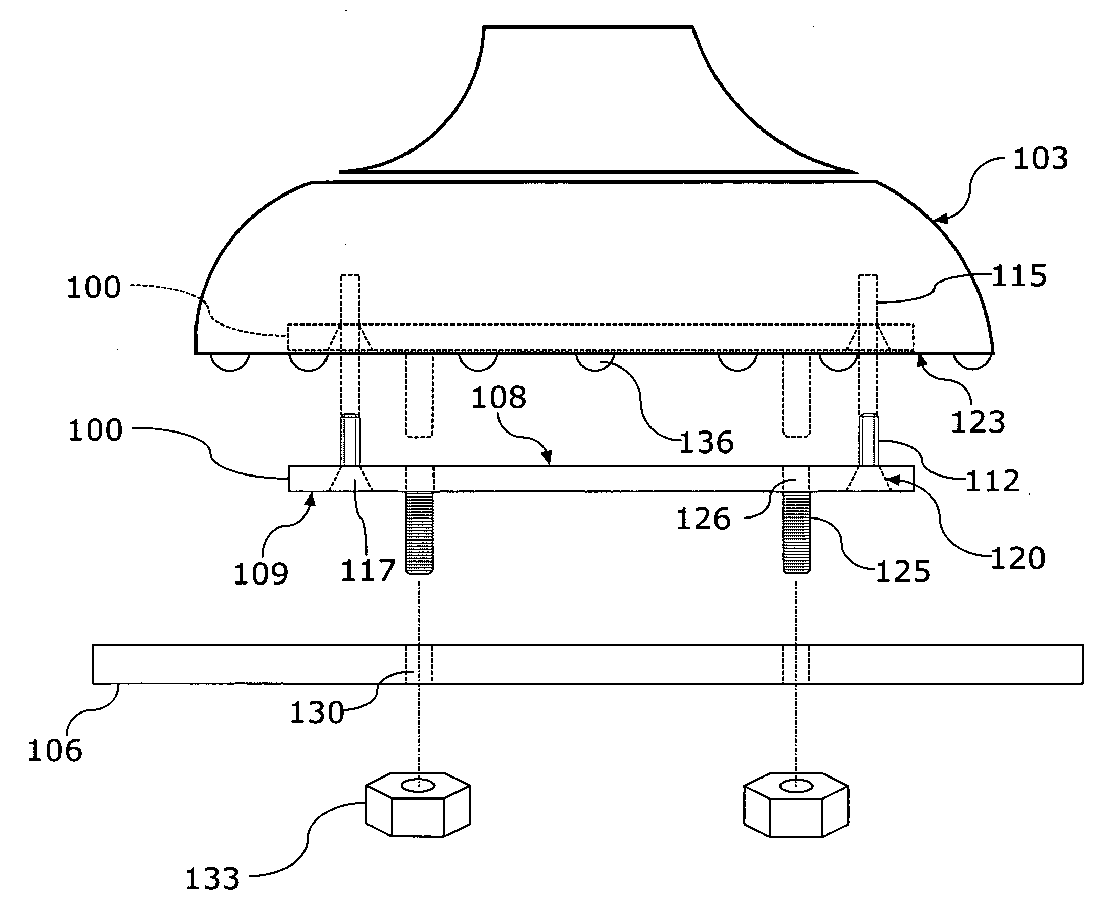
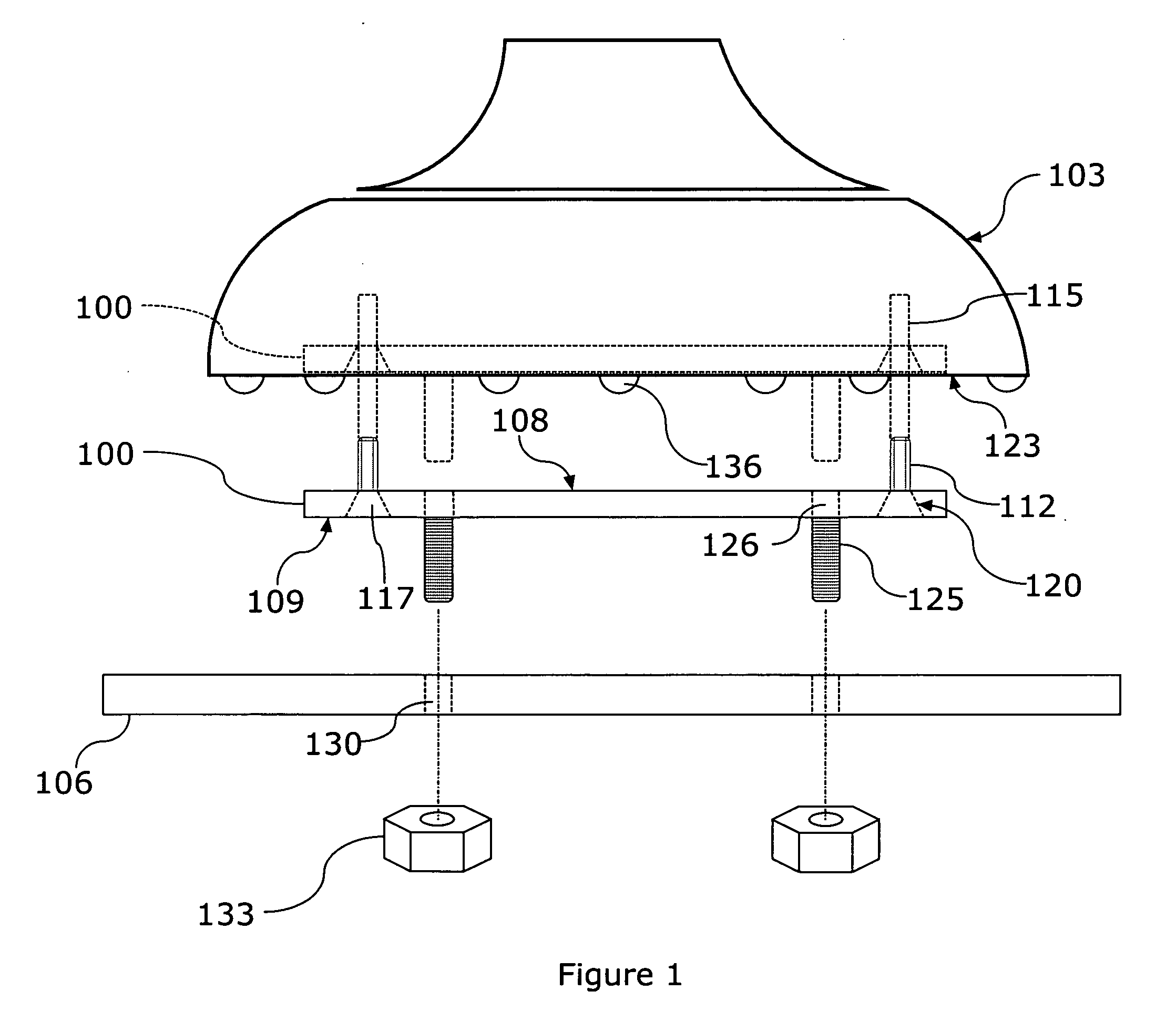
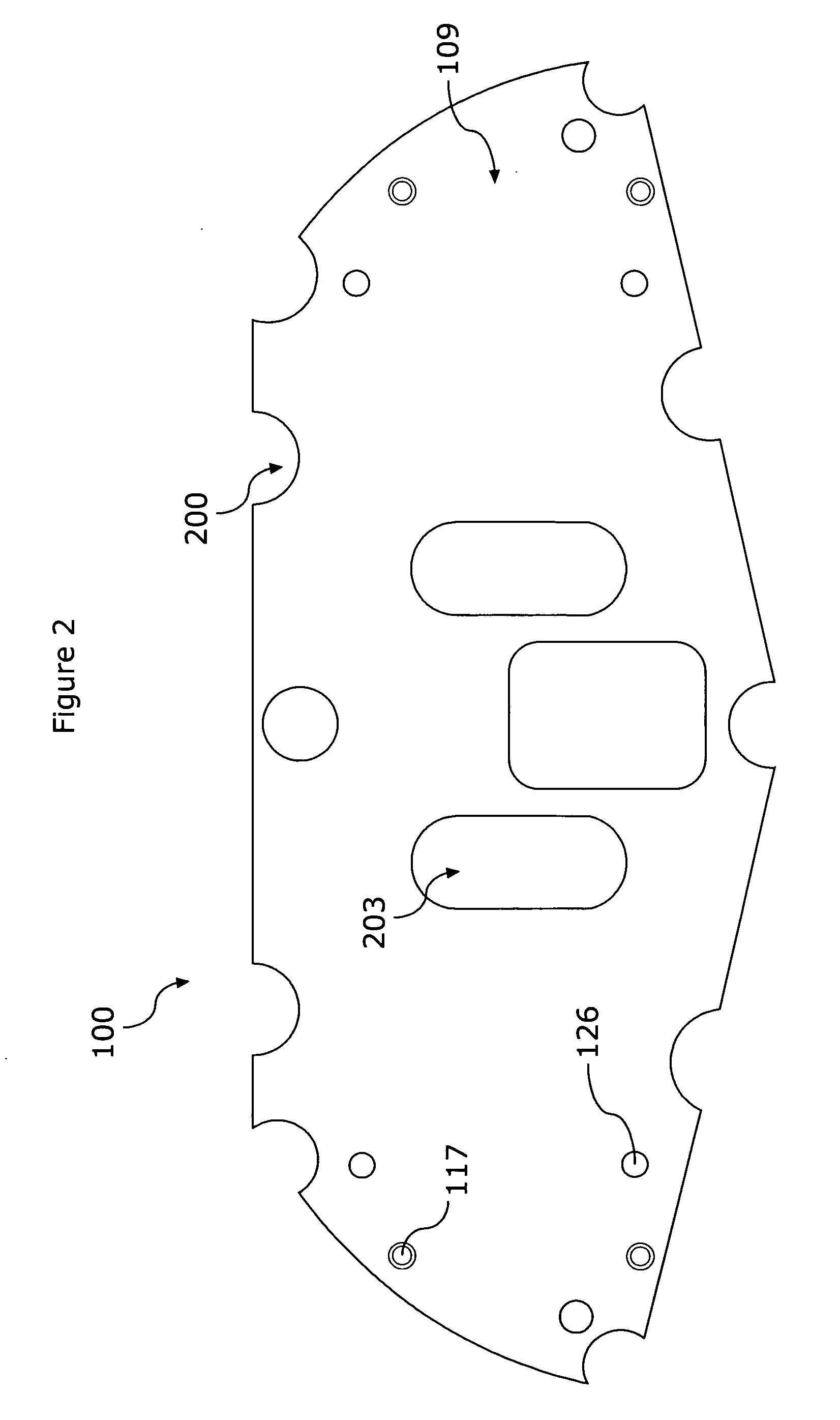
[0025]The invention summarized above and defined by the enumerated claims may be better understood by referring to the following description, which should be read in conjunction with the accompanying drawings in which like reference numbers are used for like parts. This description of an embodiment, set out below to enable one to build and use an implementation of the invention, is not intended to limit the invention, but to serve as a particular example thereof. Those skilled in the art should appreciate that they may readily use the conception and specific embodiments disclosed as a basis for modifying or designing other methods and systems for carrying out the same purposes of the present invention. Those skilled in the art should also realize that such equivalent assemblies do not depart from the spirit and scope of the invention in its broadest form.

[0026]The present invention contemplates a device for securing an electronic display, such as a television set, a computer display...


PUM


Abstract

Disclosed is a rigid bracket configured for fitted attachment to the underside of a base for an electronic display, such as a flat screen television. The bracket is shaped to fit within the outer perimeter of the base of the display and may be provided notches along the outer edge to accommodate feet that are mounted to the underside of the base of the display. The bracket is also provided a connection device for fixing the bracket (and thus the display base) to a platform on which the display is positioned.

Description

CROSS REFERENCE TO RELATED APPLICATION[0001]This application is based upon and claims benefit of copending and co-owned U.S. Provisional Patent Application Ser. No. 60 / 900,135 entitled “Anti-Theft and Anti-Tipping Device for Electronic Displays”, filed with the U.S. Patent and Trademark Office on Feb. 8, 2007, by the inventors herein, the specification of which is incorporated herein by reference in its entirety.BACKGROUND OF THE INVENTION[0002]1. Field of the Invention[0003]The invention comprises a locking and anti-tipping device for a display, such as a flat screen TV, which device secures the display to any table top or cabinet to prevent any accidental tipping and theft.[0004]2. Background of the Invention[0005]Security devices for connecting an electronic device to a surface at the base of the electronic device are shown by U.S. Pat. Nos. 3,908,942; 4,305,266; 4,613,109; 4,739,637; 5,209,445; 5,383,641; 5,697,233; 5,775,665; and 6,926,244. For example, U.S. Pat. No. 3,908,942 ...

Claims


Application Information

Patent Timeline
IPC IPC(8): H02B1/00
CPCE05B73/0082
Inventor EDWARD, EDELENDAVID, MENINGER
Owner J G EDELEN
Why Eureka
Try Eureka