Collet adapter for a motor shroud

Active Publication Date: 2009-02-26
BAKER HUGHES INC
View PDF9 Cites 6 Cited by
  • Summary
  • Abstract
  • Description
  • Claims
  • Application Information

AI Technical Summary

Benefits of technology

[0008]The collet adapter is provided to ease installation of a motor shroud onto a submersible pump as well as to ease removal of the motor shroud from a submers

Problems solved by technology

Further, this process can be difficult to implement with gl

Method used


Image

  • Collet adapter for a motor shroud
  • Collet adapter for a motor shroud
  • Collet adapter for a motor shroud

Examples


Example

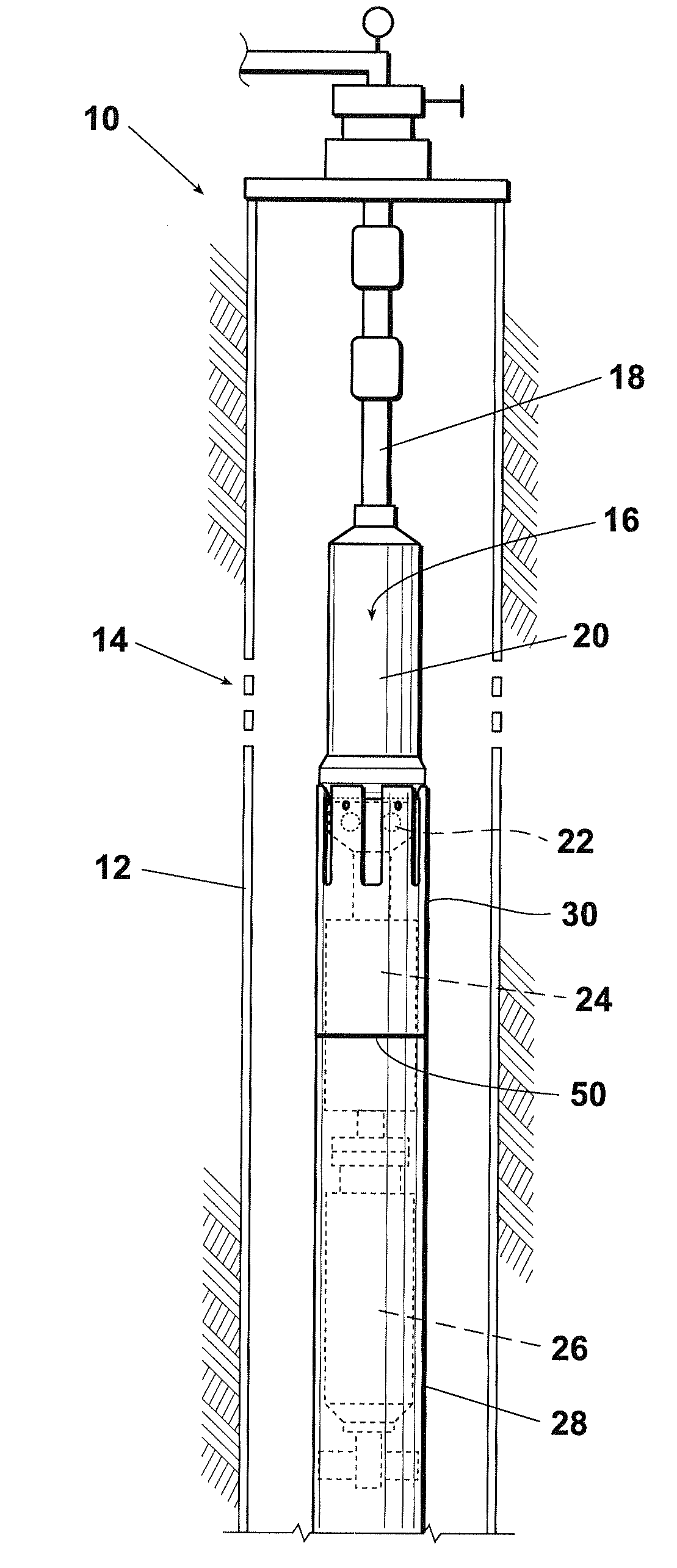
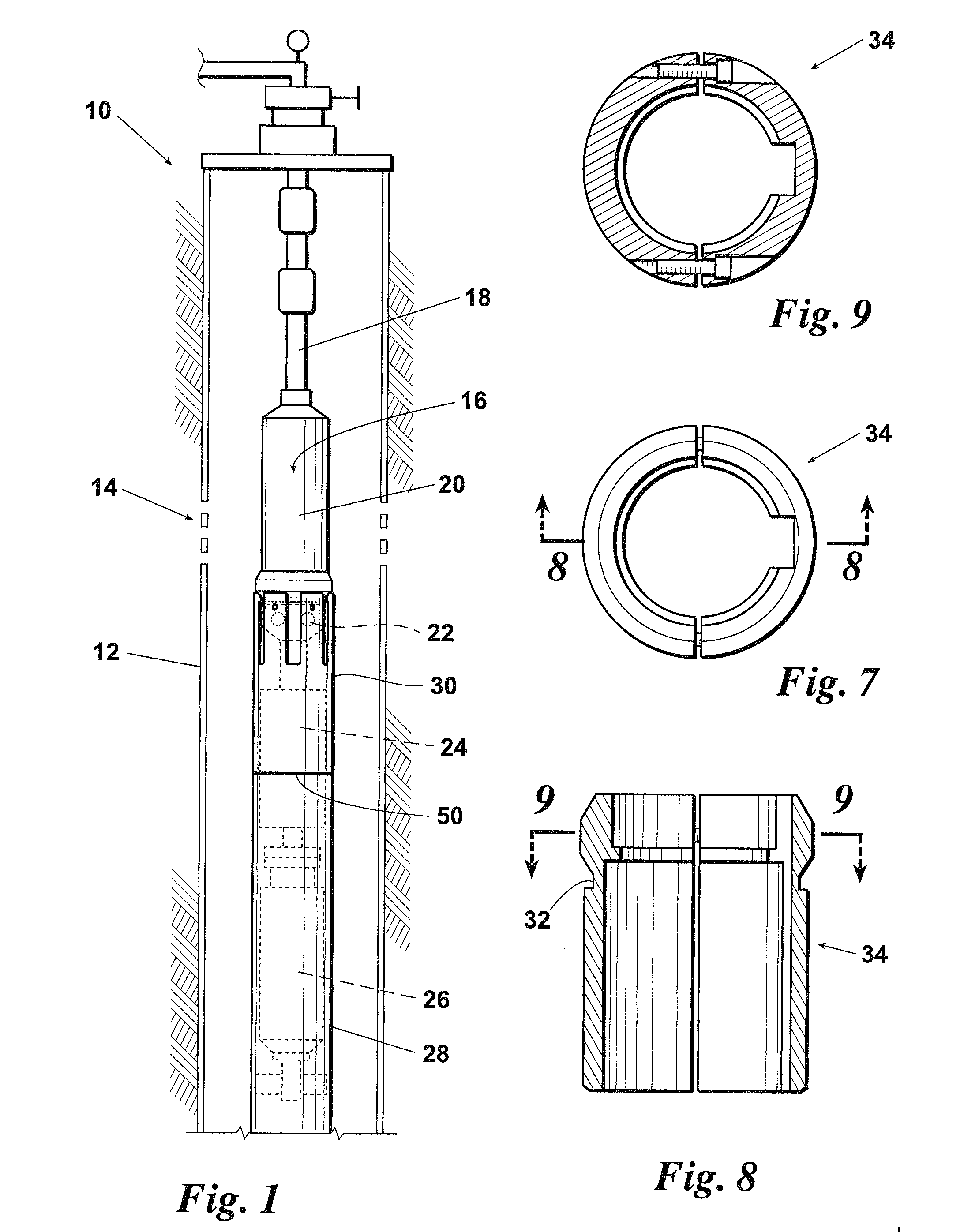
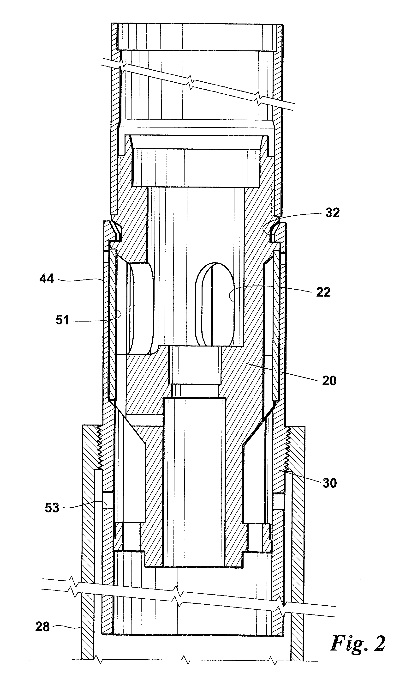
[0021]Referring first to FIG. 1, shown is a well 10 wherein casing 12 surrounds the well bore. Perforations 14 are made in the casing to allow an influx of well fluids. An electrical submersible pump assembly 16 is lowered into well 10 on tubing 18. Electrical submersible pump assembly 16 includes pump 20 having pump intakes 22 for drawing in well fluids. A seal section 24 separates pump 20 from motor 26. A motor shroud 28 may be used to direct the flow of well fluids if the electrical submersible pump assembly 16 is positioned below casing perforations 14. In this configuration, well fluids flow down from the perforations 14 around a bottom edge of motor shroud 28 where the fluid flow may be directed past motor 26 for cooling the motor before the well fluids enter pump intakes 22. Well fluids are then pumped to the surface by pump 20 through tubing 18. Motor shroud 28 is affixed to pump 20 with collet adapter 30, which is discussed in greater detail in reference to FIGS. 2-6.

[0022]...


PUM


Abstract

An electrical submersible pump assembly (ESP) includes a pump section, a motor section, and a seal section. In one embodiment, an exterior of the pump section defines a gripping indentation above the pump intake. Alternatively, a clamp member may be provided that surrounds the pump, wherein the clamp member defines the gripping indentation. A collet adapter is affixed to an upper end of a shroud. The collet adapter has gripping members that engage the gripping indentation for attaching the shroud to the electrical submersible pump assembly. The collet adapter is provided to ease installation of the motor shroud onto the ESP as well as to ease removal of the motor shroud from the ESP. The collet adapter of the present invention eliminates precise alignment and bolt-on requirements of typical motor shroud mounting techniques.

Description

FIELD OF THE INVENTION[0001]The present invention relates generally to electrical submersible pumps for producing well fluids. More particularly, the present invention relates to a collet adapter for removably attaching a motor shroud to an electrical submersible pump assembly.BACKGROUND OF THE INVENTION[0002]A typical electrical submersible pumping unit consists of an electric motor, a seal section, a multistage centrifugal pump having an appropriate intake section, a round and / or flat power cable, a motor lead extension, a motor controller and a power transformer. In addition to the basic equipment, depending on the application, several accessories may be required, such as tubing joints and couplings, swage nipples, cable guards, clamps, reels and supports, a check valve, a drain valve, centralizers, down hole pressure and temperature sending instrumentation systems, etc.[0003]The equipment, basic as well as accessories, is available in various sizes and types to meet different ap...

Claims


Application Information

Patent Timeline
IPC IPC(8): F04B17/03
CPCF04D29/628F04D13/10
Inventor IVES, JASONBRUNNER, CHRISTOPHER MARVINMCVICKER, VAN J.
Owner BAKER HUGHES INC
Why Eureka
Try Eureka