Double frame connecting structure of eyeglass frame

A spectacle frame and frame technology, which is applied in the field of double-frame connection structure, can solve the problems of high difficulty, lens drop, and time-consuming lens installation, and achieve the effect of easy installation

Inactive Publication Date: 2013-04-17
株式会社爱丽克斯
View PDF9 Cites 6 Cited by
  • Summary
  • Abstract
  • Description
  • Claims
  • Application Information

AI Technical Summary

Problems solved by technology

[0004] However, in the resin frame of the above-mentioned full mirror ring type, polyamide resin (softening temperature 90°C) and polyetherimide resin (softening temperature 170°C) are used which are higher than acetate resin (softening temperature 60°C). ), etc., if the method of heating with a heater is used, there will be a problem that the coating on the surface of the frame will peel off due to the difference in thermal expansion coefficient.
[0005] In addition, as far as the metal frame of the above-mentioned full mirror ring type is concerned, if the method of the mirror ring locking block type is adopted, the installation work of the lens must be carried out for each mirror ring, so the work efficiency is poor.
In addition, when titanium is used as the material of the frame, a special technique is required for brazing the ring lock block at the time of manufacture.
[0006] In addition, for a wooden frame made of bamboo or the like, a frame in which the entire front frame is divided up and down and the two are screwed is also known, but if such a structure is adopted, it must be The two sides of the front frame and at least three parts of the bridge of the nose are fixed by screws, so it takes man-hours to install the lens
[0007] On the other hand, in the past, only the bridge of the nose of the front frame is cut laterally, and this part is opened up and down to mount the lens on the lens ring. Since it is a structure in which the fixed connection part is inserted up and down with respect to the bridge of the nose, it is necessary to perform drilling processing in a small thickness range with high difficulty.
[0008] In addition, a spectacle frame is composed of a front frame shaped along the upper edge of the lens and a lower bezel-shaped inner frame on which the lens is mounted, and the technology of connecting them by the bridge of the nose is also known (see Patent Document 4). , because the lens is fixed on the inner frame in a semi-circular manner, there is a danger of the nylon thread breaking and the lens falling during use

Method used


Image

  • Double frame connecting structure of eyeglass frame
  • Double frame connecting structure of eyeglass frame
  • Double frame connecting structure of eyeglass frame

Examples


Embodiment 1

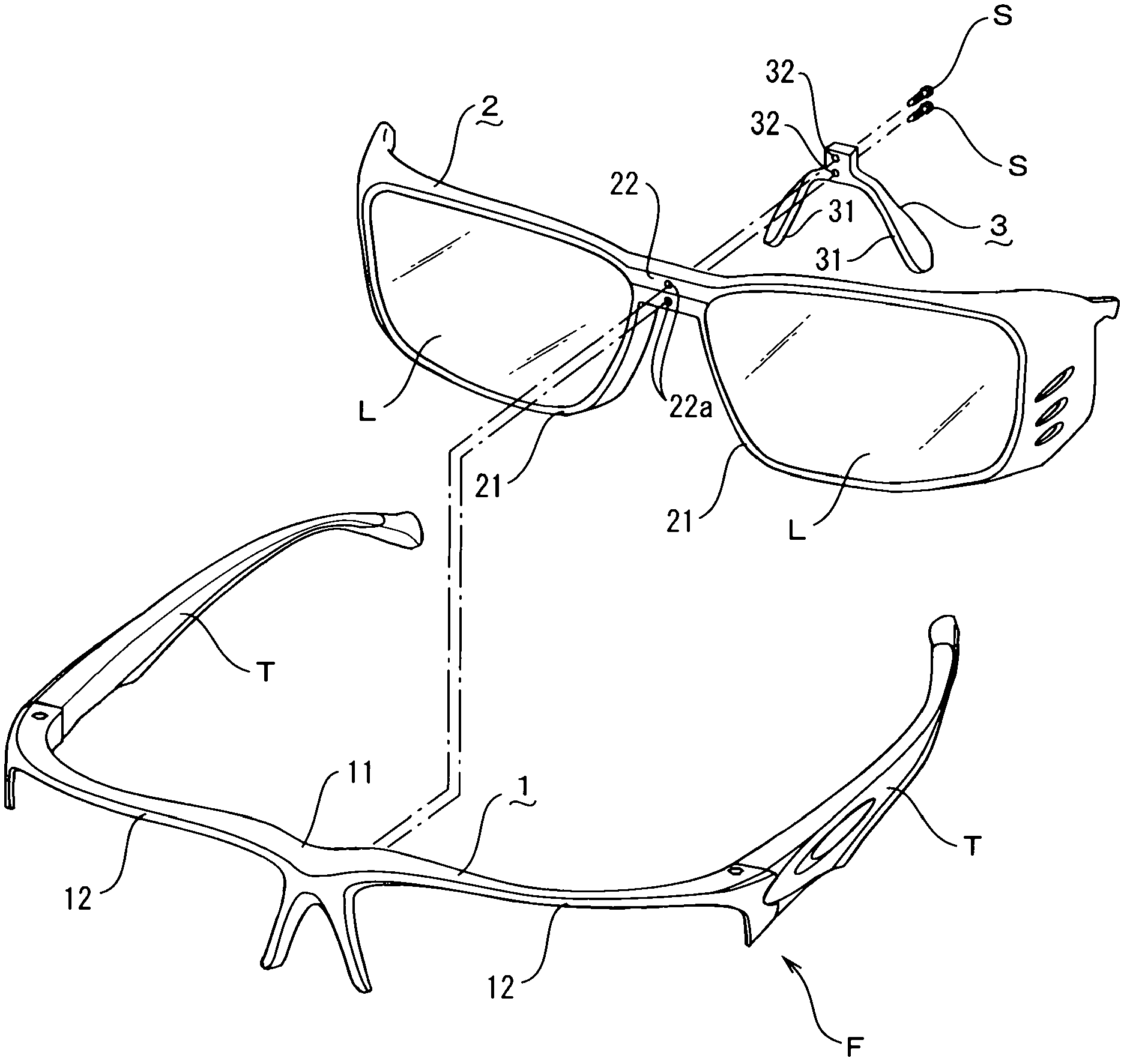
[0043] based on Figure 1 to Figure 5 , to illustrate Embodiment 1 of the present invention. In addition, in this figure, the part indicated by the symbol 1 is a holding frame, and the part indicated by the symbol 2 is an inner frame. In addition, the part indicated by the symbol 3 is a nose pad.

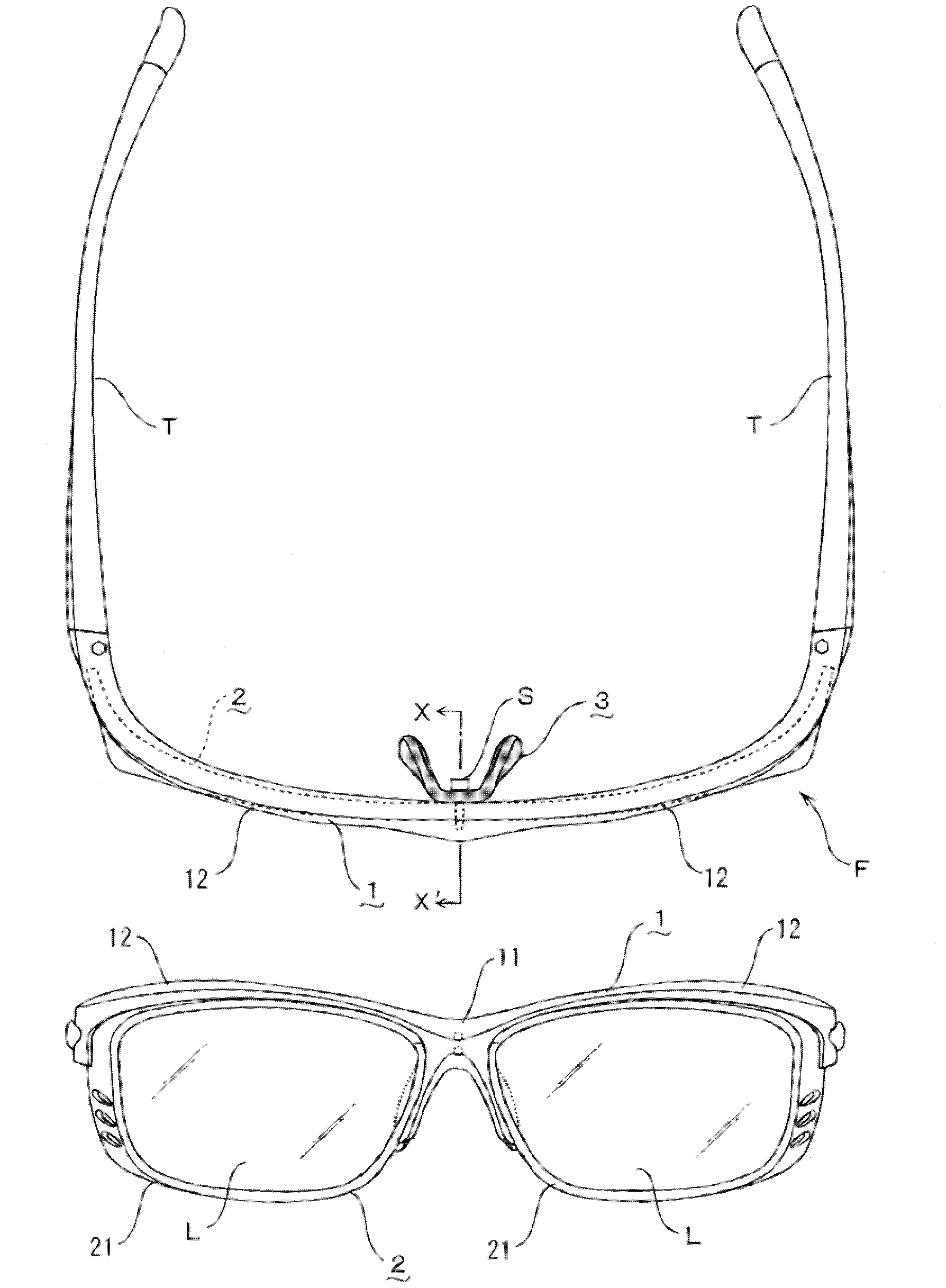
[0044] First, in Example 1, the inner frame 2 having the left and right mirror rings 21, 21 and the saddle-shaped nose pad 3 integrally having the left and right stipples 31, 31 are attached to the temples T, The back side of the brow bar type holding frame 1 of T constitutes the front part of the spectacle frame F (see figure 1 , figure 2 ).

[0045] In addition, with respect to the above-mentioned holding frame 1 and inner frame 2, lenses L, L of the inner frame 2 are arranged on the lower side of the brows 12, 12 connected from the first nose bridge 11 of the holding frame 1 to the left and right ends, so that When looking through the lenses L, L of the inner frame 2, the f...

Embodiment 2

[0055] Next, based on Figure 6 , Embodiment 2 of the present invention will be described below. In this embodiment 2, as far as the installation configuration of the holding frame 1 and the inner frame 2 is concerned, as Figure 6 As shown in (a), on the back of the first nose bridge 11 of the holding frame 1, locking protrusions 11c, 11c are arranged up and down, and the second nose bridge 22 of the inner frame 2 and the nose pad 3 are provided with the locking protrusions. The insertion holes 22a, 32 into which 11c, 11c are inserted can be Figure 6 In the state shown in (b), the inner frame 2 and the nose pad 3 are attached to the back side of the holding frame 1 .

Embodiment 3

[0057] Next, based on Figure 7 and Figure 8 , Embodiment 3 of the present invention is described as follows. In the figure, the components indicated by the symbol 4 are preceded by a box. In this embodiment 3, by connecting temple T, T on both sides and a pair of lenses L, L can be installed on the left and right lens rims 14, 14 by the holding frame 1 and the front of the holding frame 1. The front frame 4 on the side constitutes the front of the spectacle frame F (see Figure 7 ).

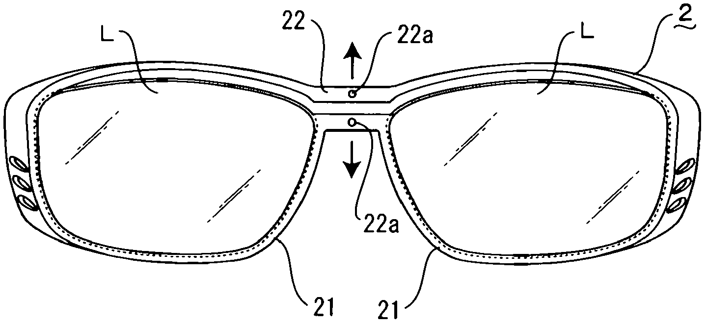
[0058] In addition, the first nose bridge 11 of the above-mentioned holding frame 1 is the same as the inner frame of embodiment 1, and its upper and lower centers are cut in the lateral direction from the inner side of one mirror ring 14 to the inner side of the other mirror ring 14. The lenses L, L are mounted in a state where the bridge of the nose 11 is opened up and down. In addition, in this embodiment, a metal frame is used as the holding frame 1 .

[0059] Furthermore, in the abov...


PUM


Abstract

Provided is a double frame connecting structure of an eyeglass frame which can effectively perform disassembling operation of an eyeglass, can avoid disbonding in a resin frame and drop of eyeglasses in use and needs no difficult manufacturing processes. The double frame connecting structure is composed of holding frames (1) possessing eyeglass legs on left and right ends and inner frames (2) assembled on back sides of the holding frames (1) and capable of installing left and right eyeglasses. The inner frames (2) possess left and right eyeglass circles; an approximate middle part from up to down of a second nose bridge combining the left and right eyeglass circles is traversely cut so that the left and right eyeglass circles can separate and combine up and down, and accordingly a pair of eyeglasses can be disassembled relative to the left and right eyeglass circles so that up and down components of a first nose bridge of the holding frames (1) and the second nose bridge of the inner frames (2) can be in mutual connection by fixing connecting assemblies.

Description

technical field [0001] The present invention relates to an improvement of a spectacle frame. Specifically, it relates to a lens mounting operation that can be efficiently carried out regardless of the material of the frame, and even when a resin frame with a high softening temperature is used, there is no coating. There is no worry about layer peeling, and the processing at the time of manufacture is also easy. The double frame connection structure of the eyeglass frame. Background technique [0002] Generally, when glasses are purchased at a retail store, a corrective lens (or a colored lens for sunglasses) is cut to match the shape of the purchased spectacle frame, mounted on the front frame, and delivered as a product. At this time, the work of attaching the lens to the front frame is usually carried out by a salesperson called an optician, but the method varies greatly depending on the type of frame. [0003] Specifically, the installation method is different because of...

Claims


Application Information

Patent Timeline
Patent Type & Authority Applications(China)
IPC IPC(8): G02C1/06G02C1/04G02C5/02G02C5/12G02C5/14G02C9/00
CPCG02C1/06G02C5/02G02C9/04
Inventor 山出重克
Owner 株式会社爱丽克斯
Why Eureka
Try Eureka