Electrifying device, process cartridge and image forming apparatus

A charging device and image technology, applied in the direction of corona discharge device, electric recording process using charge pattern, equipment for electric recording process using charge pattern, etc., can solve complex composition, difficulty in measuring and adjusting charging gap, and high cost And other issues

Inactive Publication Date: 2008-12-10
RICOH KK
View PDF17 Cites 2 Cited by
  • Summary
  • Abstract
  • Description
  • Claims
  • Application Information

AI Technical Summary

Problems solved by technology

[0025] In the methods of providing the charging gap adjustment means described in the above-mentioned Patent Document 9 and Patent Document 10, adjustments can be made according to environmental changes, but the target charging gap is a horizontal area of ​​several t...

Method used


Image

  • Electrifying device, process cartridge and image forming apparatus
  • Electrifying device, process cartridge and image forming apparatus
  • Electrifying device, process cartridge and image forming apparatus

Examples


example 1

[0251] The charging rollers A-F formed according to the above-mentioned embodiments are exemplified below,

[0252] Charging roller A

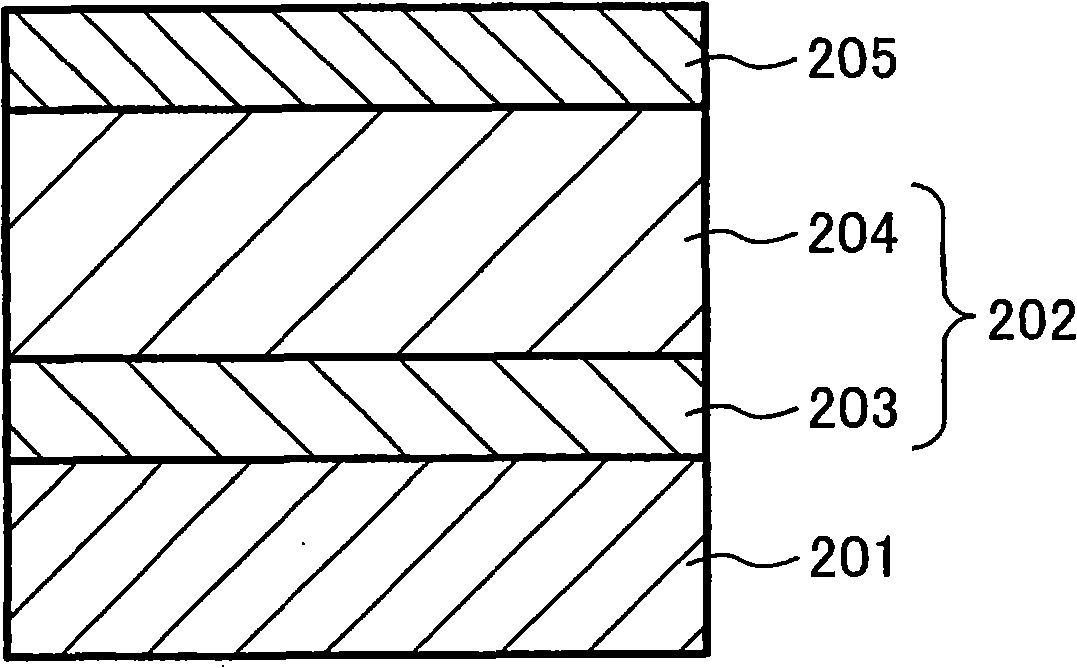
[0253] On a metal core with a diameter of 8 mm made of stainless steel, a charging layer was formed by injection molding, and the charging layer was composed of a resin composition (volume resistivity: 10 6 Ωcm), the above-mentioned resin composition is obtained by blending 60 parts by weight of an ion-conducting agent with 100 parts by weight of ABS resin, and the above-mentioned ion-conducting agent is composed of a polyolefin polymer compound having a quaternary ammonium base. A gap maintaining member was bonded to both ends of the charging layer. The gap maintaining member was composed of a polyethylene terephthalate film having a width of 8 mm and a thickness of 45 μm and an adhesive layer of 15 μm. The outer diameter of the charging layer is 11mm, making the above-mentioned charging roller (with Figure 6 constitute the same). The h...

no. 6 example

[0361] According to the sixth embodiment of the present invention, the charging roller 14 is fabricated as follows:

[0362] The charging member 14b is formed by injection molding on a metal core with a diameter of 8 mm made of stainless steel, and the charging member is made of a resin composition (volume resistivity of 10 6 Ωcm), the above-mentioned resin composition is obtained by blending 60 parts by weight of an ion-conducting agent with 100 parts by weight of ABS resin, and the above-mentioned ion-conducting agent is composed of a polyolefin polymer compound having a quaternary ammonium base.

[0363] A polyethylene gap holding member 14c was bonded to both ends of the charging member 14b, and then ground so that the difference in outer diameter between the charging member 14b and the gap holding member 14c was 50 μm, and a charging roller (with a diameter of 12 mm) was fabricated. Figure 12 constitute the same).

no. 7 example

[0364] According to the seventh embodiment of the present invention, the charging roller 14 is fabricated as follows:

[0365] The charging roller 14 was produced using the same material as that of the charging roller in the fourth embodiment described above, however, the conditions at the time of grinding were changed so that the roller wobbled greatly.


PUM

PropertyMeasurementUnit
Diameteraaaaaaaaaa
Outer diameteraaaaaaaaaa
Volume resistanceaaaaaaaaaa

Abstract

The invention relates to image forming devices such as a copier, a printer, a fax machine and a plotter, a charging unit used in the image forming devices and a manufacturing method for the charging unit, a processing cartridge and a setting method for charge gap. A charging roller 14 comprises a metal core 101 as a conductive support, a charging layer 102 made of conductive resin material, sheet-like gap holding component 103 provided between two ends of the charging layer 102. The gap holding component 103 is connected with a photosensitive layer 5b out of an image region 5a of a photoreceptor 5. Average value of the charging gaps when environmental temperature is 10 DEG C, 20 DEG C or 30 DEG C are respectively set as G10, G20, G30, satisfying the following condition: |G30-G10| X 5 is less than G20. Even in the event that a measurement device and a regulation device for the charging gaps are not provided, environmental variation of the charging gaps can still be reduced to realize high durability at low cost.

Description

[0001] This application is a divisional application of a patent application with an application date of January 10, 2005, an application number of 200510003636.2, and an invention title of "charging device, processing cartridge and image forming device". technical field [0002] The present invention relates to image forming devices such as copiers, printers, facsimile machines, plotters, etc., charging devices used in the above image forming devices and their manufacturing methods, process cartridges, and methods for setting charging gaps. Background technique [0003] In the past, as a charging device for an image forming apparatus, the mainstream is a charging method such as a scorotron, but this method has a problem of generating a large amount of discharge products such as ozone. Therefore, in recent years, a contact charging device has been widely used. A roller or a brush or the like is used as the charging member. [0004] In the charging device of the contact method...

Claims


Application Information

Patent Timeline
IPC IPC(8): G03G15/02G03G15/00G03G21/18G03G5/147F16C13/00
Inventor 小菅明朗
Owner RICOH KK
Why Eureka
Try Eureka