Vehicle far side airbag device
a technology for airbags and vehicles, applied in the direction of vehicular safety arrangments, vehicle components, pedestrian/occupant safety arrangements, etc., can solve the problems of a large swing of the upper portion and the lower portion of the bag main body
- Summary
- Abstract
- Description
- Claims
- Application Information
AI Technical Summary
Benefits of technology
Problems solved by technology
Method used
Image
Examples
first exemplary embodiment
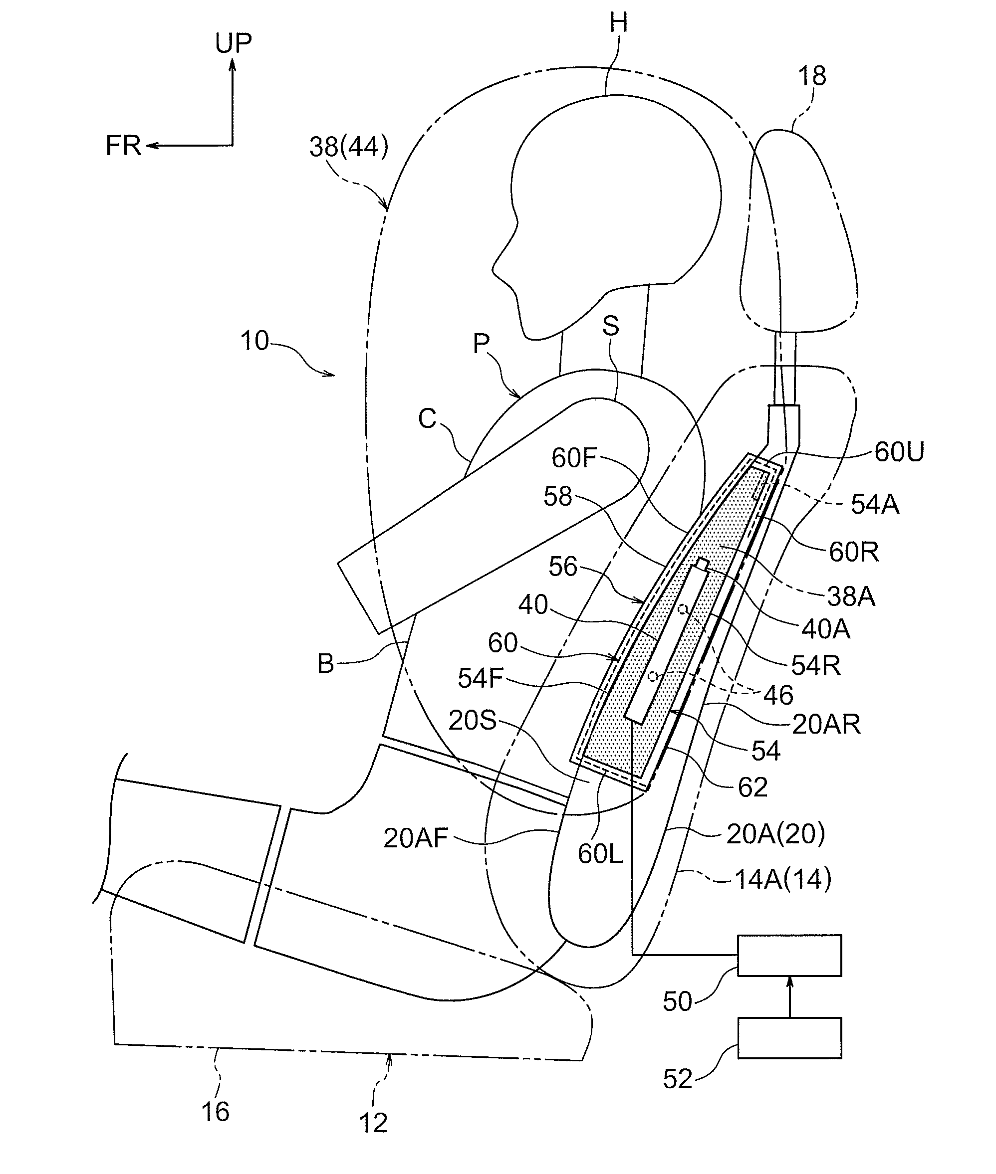
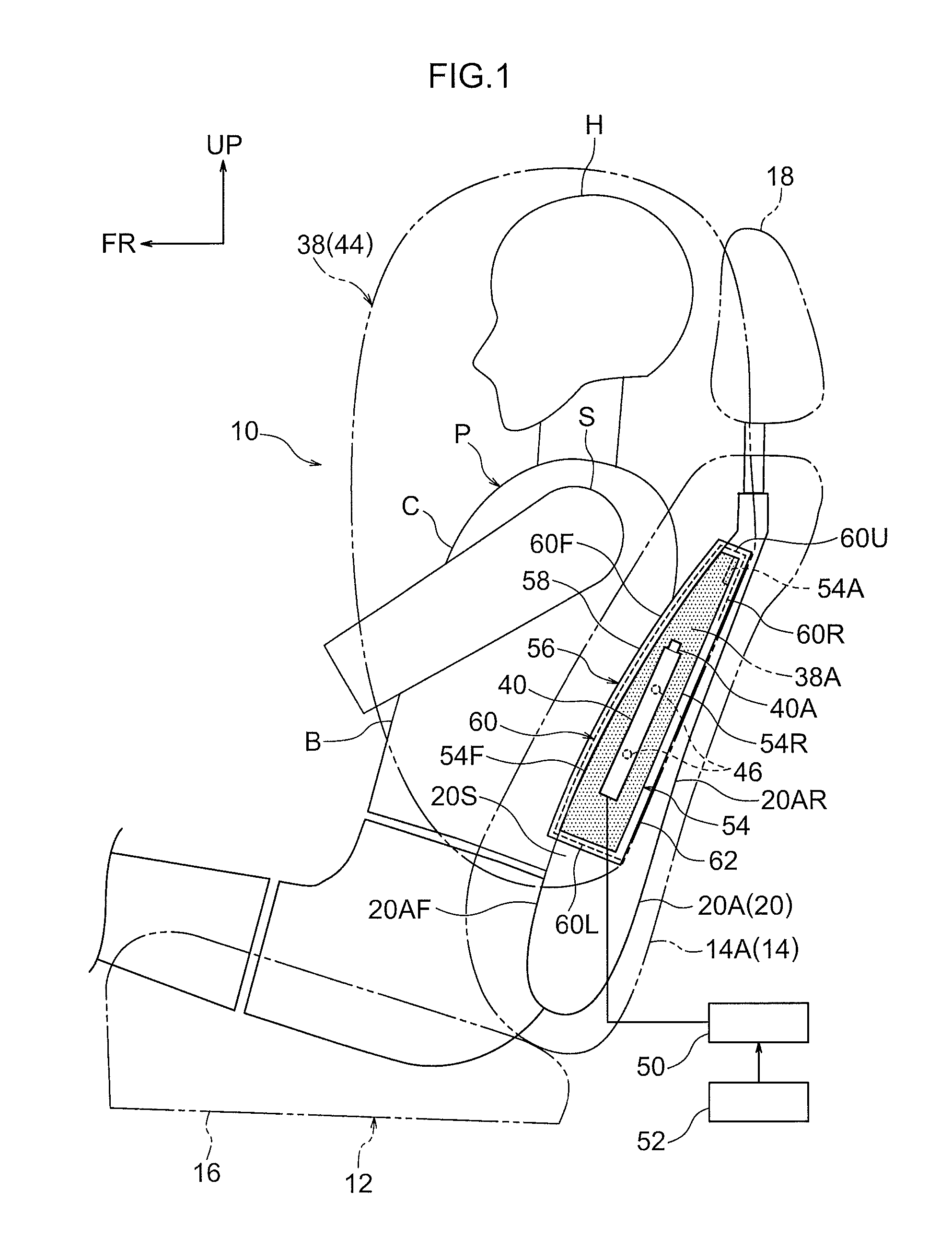
[0059]Herebelow, a vehicle far side airbag device (hereinafter referred to as “the FS airbag device”) 10 according to a first exemplary embodiment of the present invention is described using FIG. 1 to FIG. 8. An arrow FR, an arrow UP and an arrow OUT that are shown where appropriate in the drawings indicate, respectively, a forward direction (a progress direction) of the vehicle, an upward direction and outward in a width direction. Below, where descriptions are given simply using directions to longitudinal, lateral, and vertical, unless particularly specified, these refer to front and rear in the vehicle longitudinal direction, left and right in the vehicle lateral direction (the vehicle width direction), and up and down in the vehicle vertical direction.
[0060]—Structure—
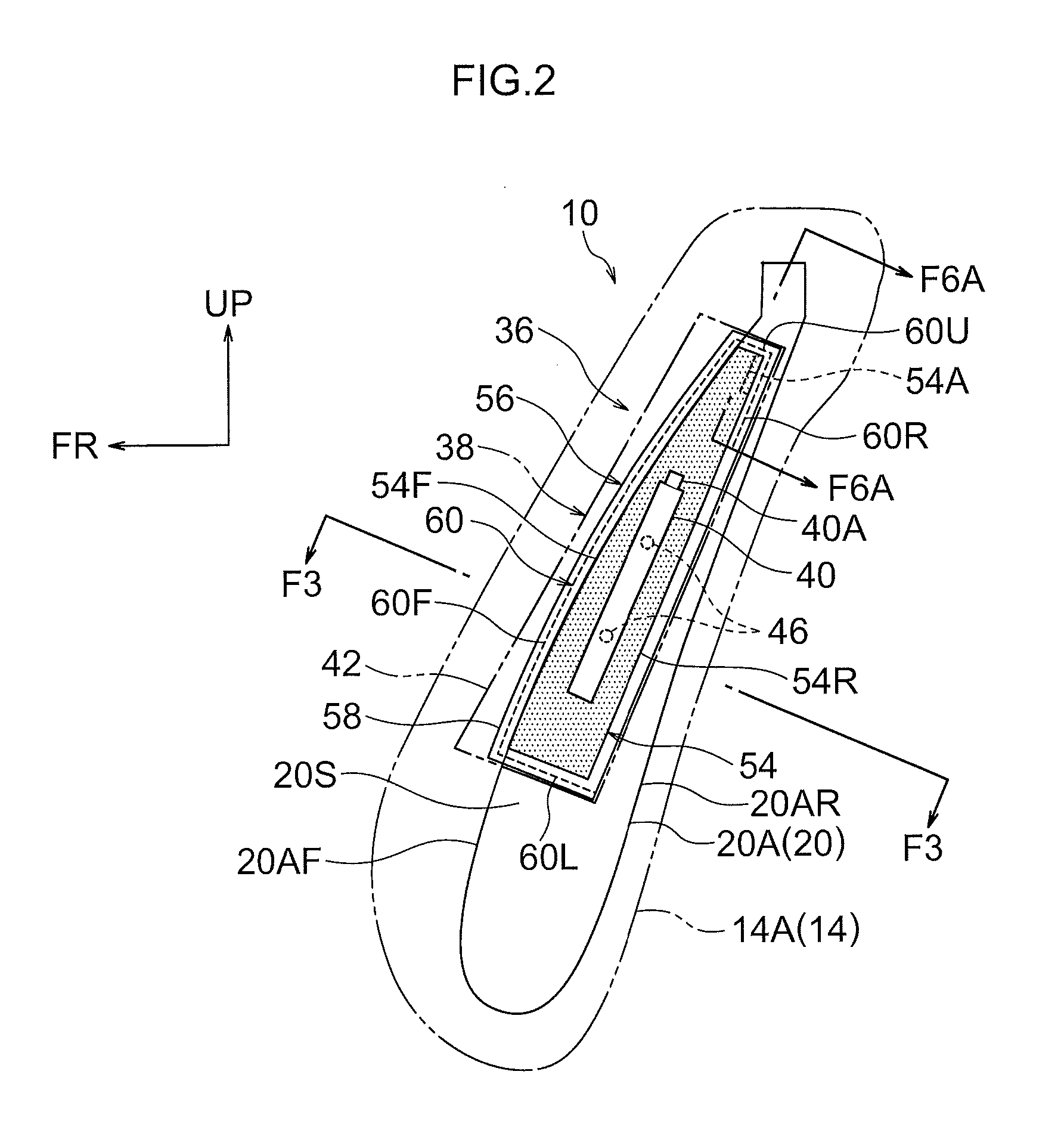
[0061]As shown in FIG. 1 to FIG. 3, the FS airbag device 10 according to the present exemplary embodiment is provided at a side portion 14A (hereinafter referred to simply as “the middle side side portion 14A”) at ...
second exemplary embodiment
[0096]FIG. 9 shows a side view in which the inflated and expanded state of the FS airbag 38 in accordance with a second exemplary embodiment of the present invention is viewed from the vehicle width direction middle side. FIG. 10 shows the inflated and expanded state of the FS airbag 38 in a schematic front view. Note that, for ease of understanding of the drawings, the bag portion 56 is not shown in the drawings of FIG. 9, FIG. 11, FIG. 12, FIG. 14, FIG. 16 to FIG. 19, FIG. 21, and FIG. 24 to FIG. 30.
[0097]In this exemplary embodiment, the inflator 40 is accommodated at the inner side of a tubular diffuser (an inner tube) 75, and the gas jetted out from the inflator 40 is distributed vertical by the diffuser 75 (see arrows G1 and G2 in FIG. 9). In addition, in this exemplary embodiment a non-inflating portion 72 for inflation regulation is provided at a vertical direction middle portion of the FS airbag 38 (a central side if the inflated and expanded state of the FS airbag 38 is vi...
third exemplary embodiment
[0101]FIG. 11 shows a side view in which the inflated and expanded state of the FS airbag 38 in accordance with a third exemplary embodiment of the present invention is viewed from the vehicle width direction middle side thereof In this exemplary embodiment, the FS airbag 38 is partitioned into a front chamber 88 and a rear chamber 90 by a partition portion 86. Other structures are the same as in the first exemplary embodiment.
[0102]The above-mentioned partition portion 86 is structured by a stitched portion at which the base cloth 44 is stitched. The partition portion 86 is provided with an upper-and-lower partition portion 86A at a vertical direction central portion of the FS airbag 38 and a longitudinal partition portion 86B at a longitudinal direction central portion of the FS airbag 38. The upper-and-lower partition portion 86A extends toward the central side from the rear end side of the FS airbag 38. The longitudinal partition portion 86B extends toward the central side from ...
PUM
 Abstract
Description
Claims
Application Information
 - R&D
- Intellectual Property
- Life Sciences
- Materials
- Tech Scout
- Unparalleled Data Quality
- Higher Quality Content
- 60% Fewer Hallucinations
Browse by: Latest US Patents, China's latest patents, Technical Efficacy Thesaurus, Application Domain, Technology Topic, Popular Technical Reports.
© 2025 PatSnap. All rights reserved.Legal|Privacy policy|Modern Slavery Act Transparency Statement|Sitemap|About US| Contact US: help@patsnap.com


