
Mobile electronic device

a mobile electronic and device technology, applied in the field of electronic devices, can solve the problems of inconvenient utilization and likely upper body, and achieve the effects of stable support of rotating elements, good operability, and reduced sway chan

Inactive Publication Date: 2012-06-07
COMPAL ELECTRONICS INC
View PDF7 Cites 18 Cited by
  • Summary
  • Abstract
  • Description
  • Claims
  • Application Information

AI Technical Summary

Benefits of technology

[0021]In an embodiment of the invention, the rotating element is connected to the first body through a hinge to facilitate the second body rotating relative to the first body.
[0032]According to the above descriptions, the pivot mechanism has the supporting element pivoted to the rotating element, and after the second body is tilted from the first body through a pivot rotation of the rotating element, the supporting element is suitable for pivotally rotating relative to the rotating element to lean against the first body, so as to stably support the rotating element and the second body. In this way, when the user presses the second body to perform the touch operation, the second body can be supported by the supporting element to reduce a chance of sway, so that the mobile electronic device may have good operability. Moreover, the elastic element can be configured between the rotating element and the supporting element, so that the supporting element is adapted to be automatically popped up from the rotating element through an elastic force of the elastic element, so as to facilitate the operation of the user.

Problems solved by technology

However, when the user performs the touch operation on the upper body tilted from the lower body, the upper body is probably swayed due to a pressing operation of the user, which is inconvenient in utilization.

Method used


Image

  • Mobile electronic device
  • Mobile electronic device
  • Mobile electronic device

Examples


Embodiment Construction

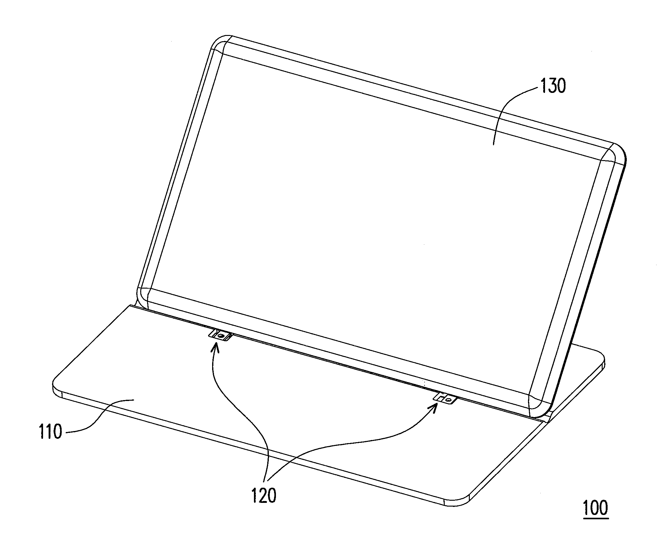
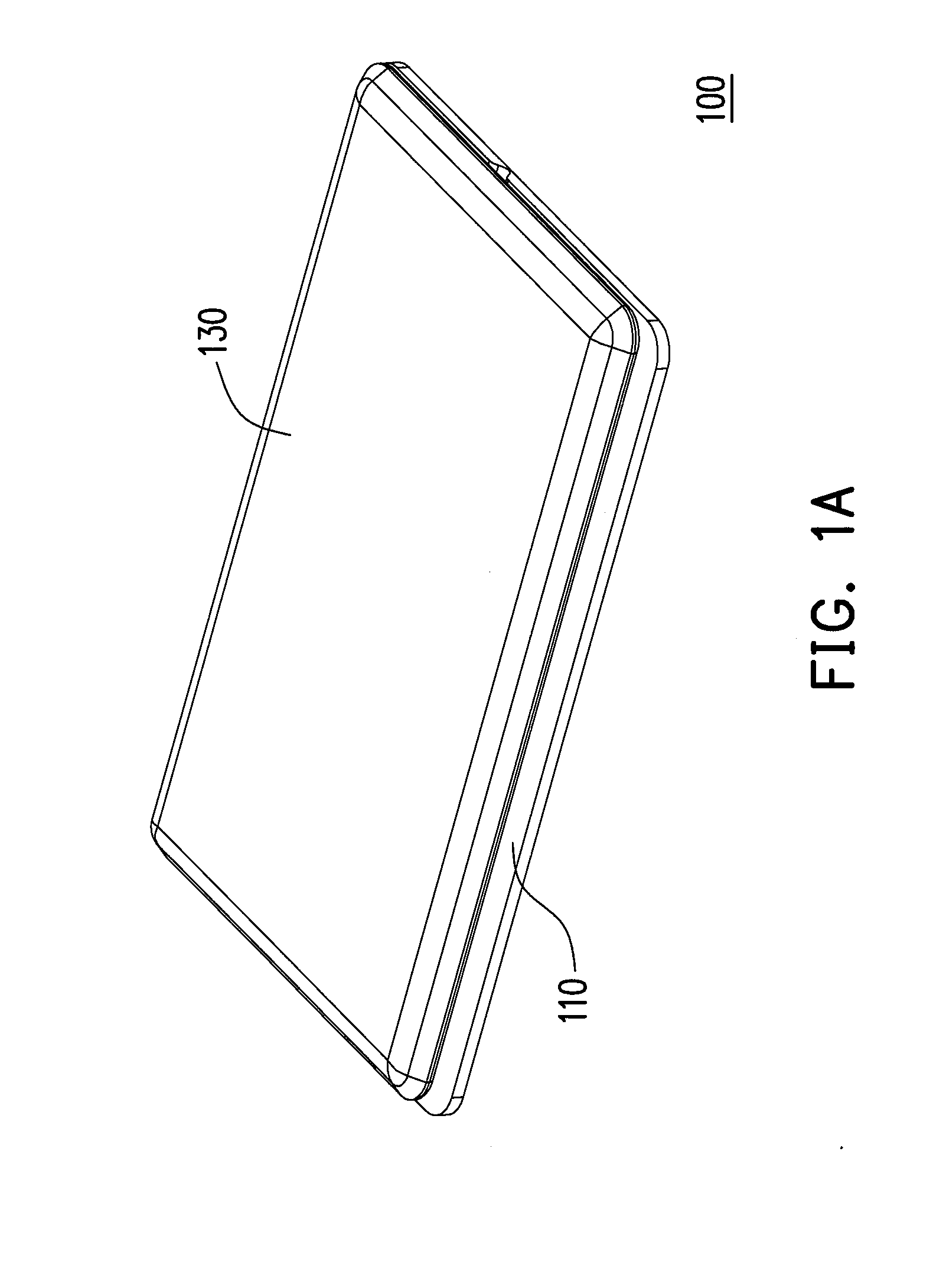
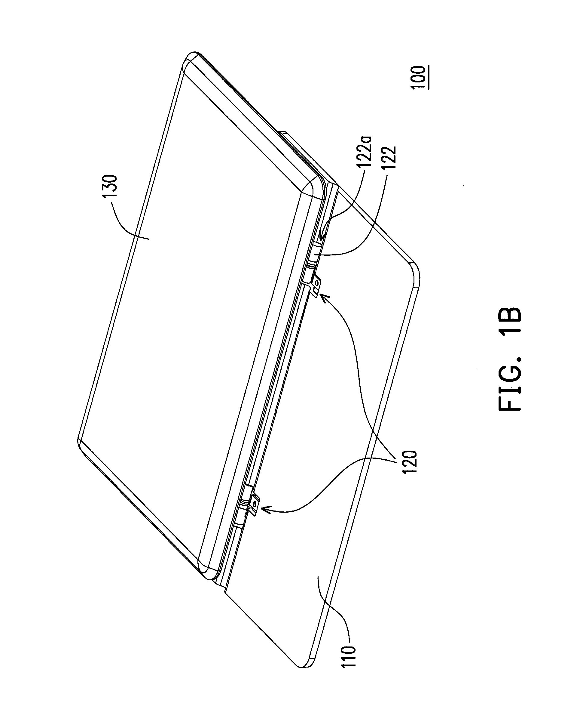
[0043]FIGS. 1A-1C are diagrams illustrating an actuation of a mobile electronic device according to an embodiment of the invention. Referring to FIGS. 1A-1C, the mobile electronic device 100 of the present embodiment includes a first body 110, a pivot mechanism 120 (two pivot mechanisms are illustrated) and a second body 130. The pivot mechanism 120 is connected between the first body 110 and the second body 130. The second body 130 is adapted to cover a part of the first body 110 and exposes another part of the first body 110 as that shown in FIG. 1A. The second body 130 can be slided relative to the first body 110 from a state shown in FIG. 1A to a state shown in FIG. 1B, and is rotated relative to the first body 110 to a state shown in FIG. 1C. The second body 130 includes a touch interface for controlling a display on the second body 130. The mobile electronic device 100 of the present embodiment is, for example, a mobile phone or a tablet PC, and the first body 110 and the seco...


PUM


Abstract

A mobile electronic device includes a first body, a pivot mechanism and a second body. The pivot mechanism includes a rotating element and a supporting element. The rotating element is connected between the first body and the second body to facilitate rotating the second body relatively to the first body. The rotating element includes a guiding trench connected to the second body, and the second body is suitable for sliding relatively to the first body. The supporting element is pivoted to the rotating element or the second body. When the second body slides to drive the rotating element to a rotating position, the rotating element is rotated relatively to the first body to drive the second body for tilting from the first body, and the supporting element is suitable of rotating relatively to the rotating element or the second body to provide a supporting force to the second body.

Description

CROSS-REFERENCE TO RELATED APPLICATION[0001]This application claims the priority benefits of U.S. provisional application Ser. No. 61 / 418,882, filed on Dec. 2, 2010. The entirety of each of the above-mentioned patent application is hereby incorporated by reference herein and made a part of this specification.BACKGROUND OF THE INVENTION[0002]1. Field of the Invention[0003]The invention relates to an electronic device. Particularly, the invention relates to a mobile electronic device.[0004]2. Description of Related Art[0005]Along with development of information technology, it becomes easier to obtain required information from electronic devices in daily life. On the other hand, with improvement of processing techniques, various mobile electronic devices are developed to have features of lightness, slimness, shortness and smallness, and due to the characteristic and advantage of portability, the mobile electronic devices are widely applied in daily life.[0006]Taking a mobile phone as a...

Claims


Application Information

Patent Timeline
Patent Type & Authority Applications(United States)
IPC IPC(8): H05K5/02
CPCG06F1/1624G06F1/1616
Inventor CHEN, JUO-TILIN, PO-ANLING, KUO-NANCHEN, YUNG-HUI
Owner COMPAL ELECTRONICS INC
Learn More