Vehicle far side airbag device

a technology for airbags and vehicles, applied in the direction of vehicular safety arrangments, vehicle components, pedestrian/occupant safety arrangements, etc., can solve the problems of a large swing of the upper portion and the lower portion of the bag main body

Active Publication Date: 2017-01-03
TOYOTA JIDOSHA KK
View PDF16 Cites 16 Cited by
  • Summary
  • Abstract
  • Description
  • Claims
  • Application Information

AI Technical Summary

Benefits of technology

[0010]In the first aspect, when the inflator provided in the side portion at the vehicle width direction middle side of the seatback of the vehicle seat is operated, the far side airbag is inflated and expanded by the gas for inflation that is generated from the inflator. The far side airbag is fixed to the seat frame using the stud bolts of the inflator, and includes the support plate retention portion at the face opposite the side face of the seat frame. The support plate is retained at the support plate retention portion and the support plate is fixed to the seat frame using the stud bolts of the inflator. The support plate is formed to be elongated to both sides in the vehicle vertical direction relative to the inflator and is engaged with the seat frame at the vehicle upper side relative to the inflator. During the inflation and expansion of the far side airbag, the support plate supports the far side airbag at both sides in the vehicle vertical direction of the inflator. Consequently, swinging of an upper portion and lower portion of the far side airbag may be reduced, which contributes to stabilization of the expansion action of the far side airbag.
[0012]In the second aspect, the bag portion is provided at the far side airbag, at the face opposite the side face of the seat frame. Thus, the support plate may be retained at the face opposite of the far side airbag by a simple structure.
[0014]In the third aspect, the upper end portion of the support plate is engaged with the seat frame by the hook portion formed at the upper end portion of the support plate being hooked onto the seat frame. Thus, the upper end portion of the support plate may be engaged with the seat frame by a simple structure.
[0016]In the fourth aspect, in the inflated and expanded state of the far side airbag, the upper end portion of the support plate is disposed as described above. Therefore, during the inflation and expansion of the far side airbag, during restraint of an occupant and the like, unintended folding of the lower end of the non-inflating portion of the far side airbag may be prevented or inhibited.
[0018]In the fifth aspect, in the inflated and expanded state of the far side airbag, the upper end portion of the support plate is disposed as described above. Therefore, during the inflation and expansion of the far side airbag, during restraint of an occupant and the like, unintended folding of the upper-and-lower partition portion of the far side airbag may be prevented or inhibited.
[0021]As described above, a vehicle far side airbag device according to the present invention contributes to stabilization of the expansion action of a far side airbag.

Problems solved by technology

Therefore, when the bag main body is being inflated and expanded by the gas for inflation, there may be great swinging of an upper portion and a lower portion of the bag main body.

Method used


Image

  • Vehicle far side airbag device
  • Vehicle far side airbag device
  • Vehicle far side airbag device

Examples


first exemplary embodiment

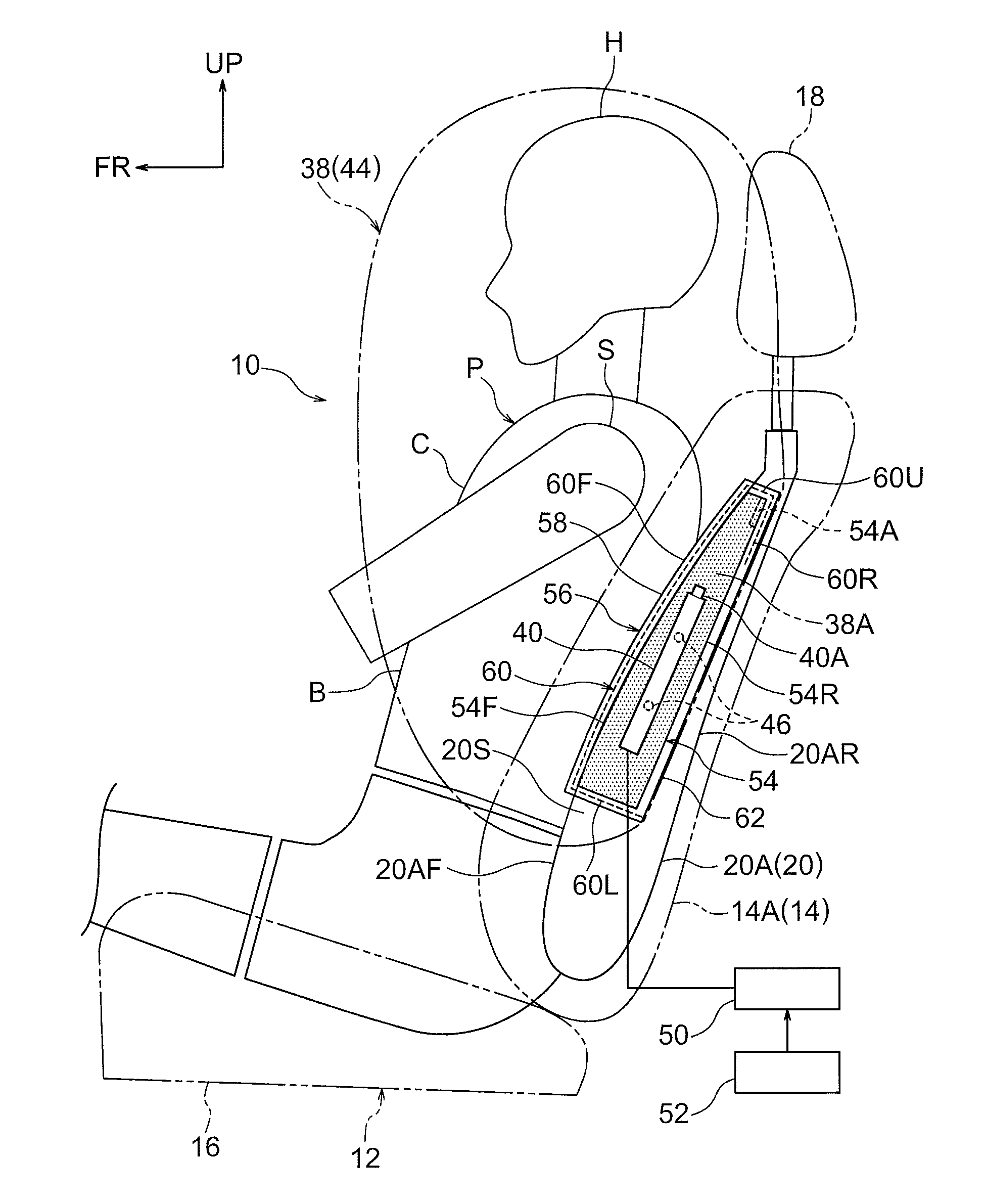
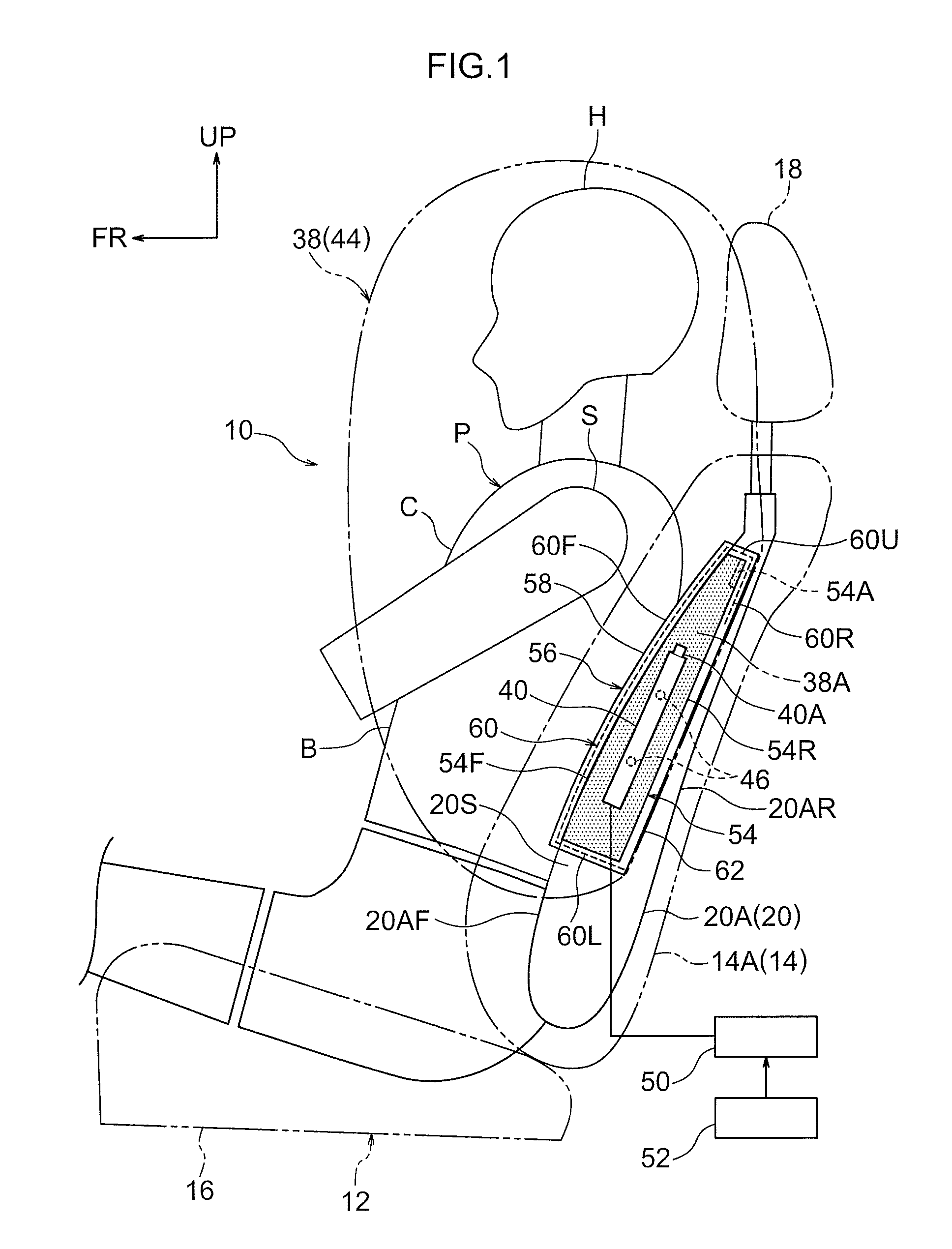
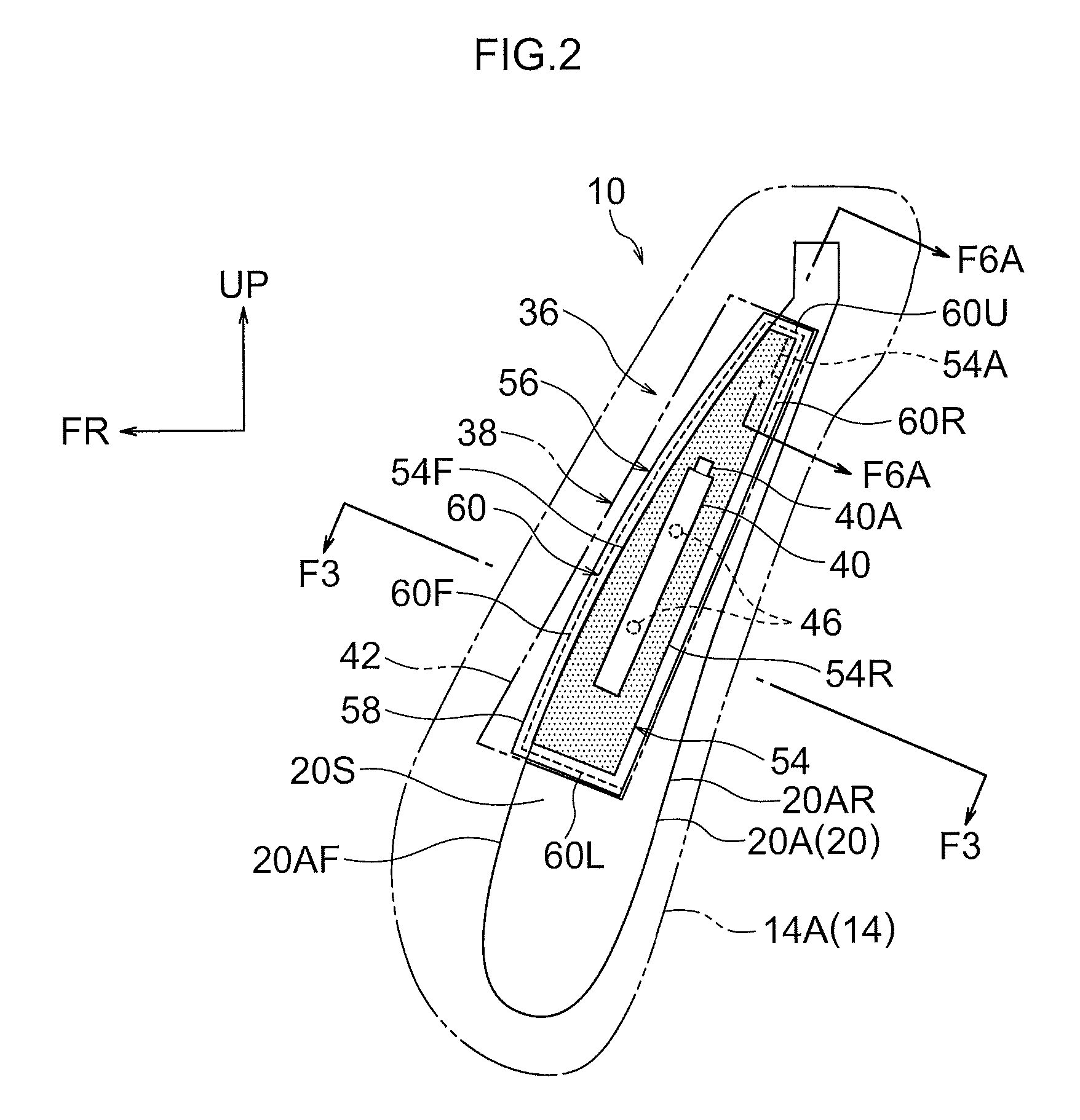
[0059]Herebelow, a vehicle far side airbag device (hereinafter referred to as “the FS airbag device”) 10 according to a first exemplary embodiment of the present invention is described using FIG. 1 to FIG. 8. An arrow FR, an arrow UP and an arrow OUT that are shown where appropriate in the drawings indicate, respectively, a forward direction (a progress direction) of the vehicle, an upward direction and outward in a width direction. Below, where descriptions are given simply using directions to longitudinal, lateral, and vertical, unless particularly specified, these refer to front and rear in the vehicle longitudinal direction, left and right in the vehicle lateral direction (the vehicle width direction), and up and down in the vehicle vertical direction.

[0060]—Structure—

[0061]As shown in FIG. 1 to FIG. 3, the FS airbag device 10 according to the present exemplary embodiment is provided at a side portion 14A (hereinafter referred to simply as “the middle side side portion 14A”) at ...

second exemplary embodiment

[0096]FIG. 9 shows a side view in which the inflated and expanded state of the FS airbag 38 in accordance with a second exemplary embodiment of the present invention is viewed from the vehicle width direction middle side. FIG. 10 shows the inflated and expanded state of the FS airbag 38 in a schematic front view. Note that, for ease of understanding of the drawings, the bag portion 56 is not shown in the drawings of FIG. 9, FIG. 11, FIG. 12, FIG. 14, FIG. 16 to FIG. 19, FIG. 21, and FIG. 24 to FIG. 30.

[0097]In this exemplary embodiment, the inflator 40 is accommodated at the inner side of a tubular diffuser (an inner tube) 75, and the gas jetted out from the inflator 40 is distributed vertical by the diffuser 75 (see arrows G1 and G2 in FIG. 9). In addition, in this exemplary embodiment a non-inflating portion 72 for inflation regulation is provided at a vertical direction middle portion of the FS airbag 38 (a central side if the inflated and expanded state of the FS airbag 38 is vi...

third exemplary embodiment

[0101]FIG. 11 shows a side view in which the inflated and expanded state of the FS airbag 38 in accordance with a third exemplary embodiment of the present invention is viewed from the vehicle width direction middle side thereof. In this exemplary embodiment, the FS airbag 38 is partitioned into a front chamber 88 and a rear chamber 90 by a partition portion 86. Other structures are the same as in the first exemplary embodiment.

[0102]The above-mentioned partition portion 86 is structured by a stitched portion at which the base cloth 44 is stitched. The partition portion 86 is provided with an upper-and-lower partition portion 86A at a vertical direction central portion of the FS airbag 38 and a longitudinal partition portion 86B at a longitudinal direction central portion of the FS airbag 38. The upper-and-lower partition portion 86A extends toward the central side from the rear end side of the FS airbag 38. The longitudinal partition portion 86B extends toward the central side from...


PUM


Abstract

In a vehicle far side airbag device, a far side airbag is fixed to a seatback frame using stud bolts of an inflator. The far side airbag includes a bag portion at a face opposite a side face of the seatback frame. A support plate is retained in the bag portion and is fixed to the seatback frame using the stud bolts. The support plate is formed to be longer to both sides in a vehicle vertical direction than the inflator, and is engaged with the seatback frame at the vehicle upper side relative to the inflator. During inflation and expansion of the far side airbag, the support plate supports the far side airbag at both sides in the vehicle vertical direction of the inflator.

Description

CROSS-REFERENCE TO RELATED APPLICATION[0001]This application is based on and claims priority under 35 USC 119 from Japanese Patent Application No. 2014-245259, filed on Dec. 3, 2014, which is incorporated by reference herein.TECHNICAL FIELD[0002]The present invention relates to a vehicle far side airbag device equipped with a far side airbag that inflates and expands from a side portion at a vehicle width direction middle side of a seatback of a vehicle seat.RELATED ART[0003]An airbag device (a far side airbag device) recited in Japanese Patent Application Laid-Open (JP-A) No. 2014-054956 is installed in a vehicle in which plural seats are arranged side by side. When an impact force acts from one side of the arrangement direction of the plural seats, this airbag device causes an airbag to inflate, so as to protrude in a direction to forward of an occupant, from a rear-reclining portion of a seat at a further side (a far side) that is further from the side at which the impact force a...

Claims


Application Information

Patent Timeline
Patent Type & Authority Patents(United States)
IPC IPC(8): B60R21/16B60R21/207B60R21/231B60R21/2338
CPCB60R21/207B60R21/2338B60R21/23138B60R2021/161B60R2021/23146B60R2021/23161B60R2021/23382B60R2021/23386
Inventor FUJIWARA, YUSUKE
Owner TOYOTA JIDOSHA KK
Why Eureka
Try Eureka