Lens tube and mounting base thereof

a technology of lens tube and mounting base, which is applied in the direction of printers, instruments, camera focusing arrangement, etc., can solve the problems of people's increasing demands on image resolution, and achieve the effect of preventing dust contamination

Active Publication Date: 2007-12-25
LARGAN PRECISION
View PDF4 Cites 18 Cited by
  • Summary
  • Abstract
  • Description
  • Claims
  • Application Information

AI Technical Summary

Benefits of technology

[0008]The primary objective of the present invention is to provide a lens tube and a mounting base thereof, wherein a first conical surface of the lens tube and a second conical surface of the mounting base can cooperate with each other to prevent dust contamination and to make the central axis aligned with the optical axis. The present invention comprises a lens tube, a mounting base, a lens array and an image sensor. The objectives of the present invention are described below:
[0010]One important characteristic of the present invention is that the lens tube has a first conical surface, the mounting base has a second conical surface, and the two conical surfaces are engaged with each other. The engagement of the first and second conical surfaces can enable the central axis of the lens tube and the mounting base to be positioned more stably. The central axis and the optical axis will not deviate even after long time of use, so that the optical signal of the object to be shot can be focused and transmitted precisely to the image sensor. In addition, it can alleviate the wobbles of the lens tube and the mounting base.
[0011]The more important characteristic of the present invention is that the locking portion of the lens tube is formed between an inner periphery and an outer periphery of the lens tube for mating with the locking portion of the mounting base, such arrangement can prevent dust contamination.

Problems solved by technology

Nowadays, people's demand on image resolution is becoming increasingly strict.

Method used


Image

  • Lens tube and mounting base thereof
  • Lens tube and mounting base thereof
  • Lens tube and mounting base thereof

Examples


Embodiment Construction

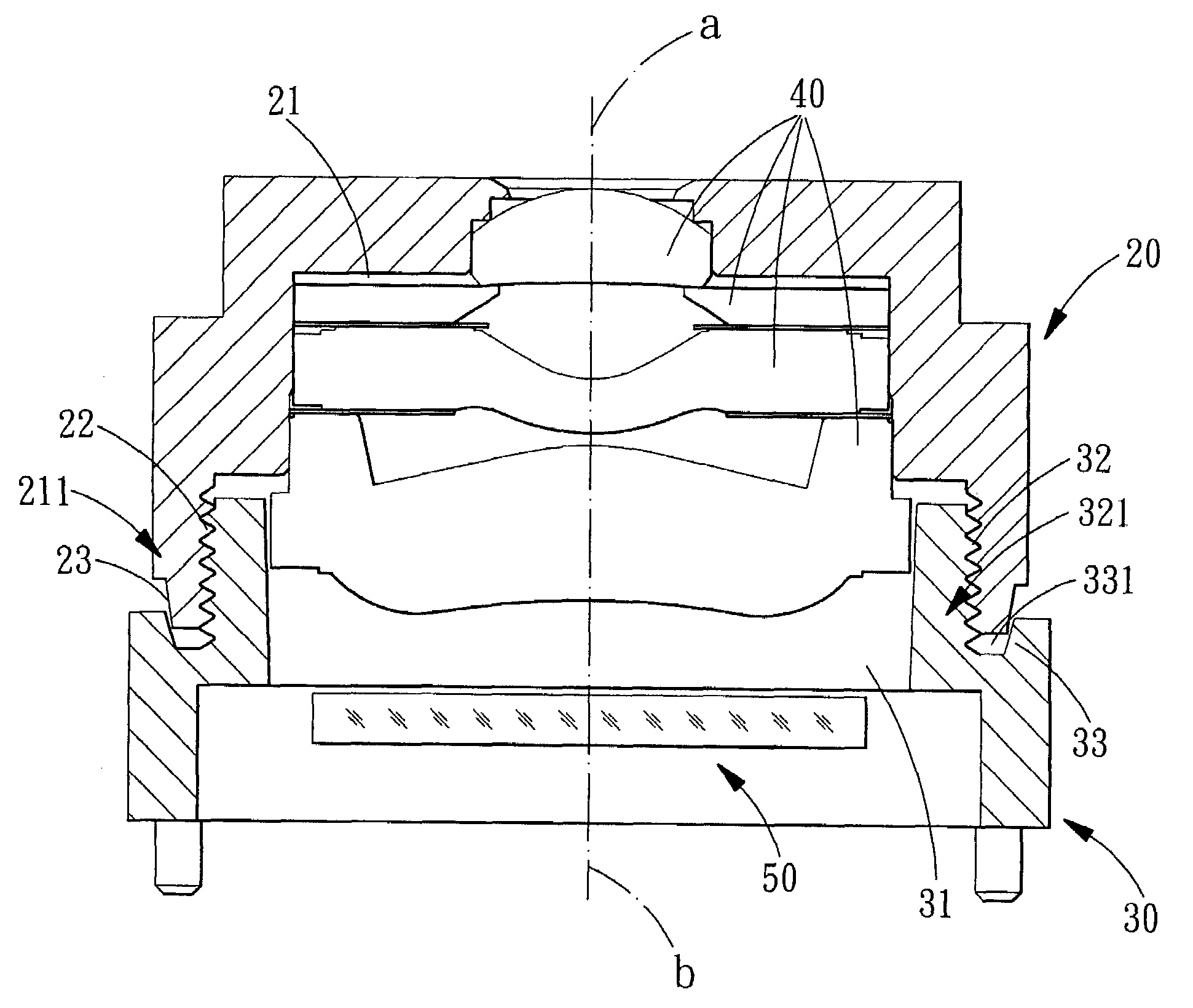
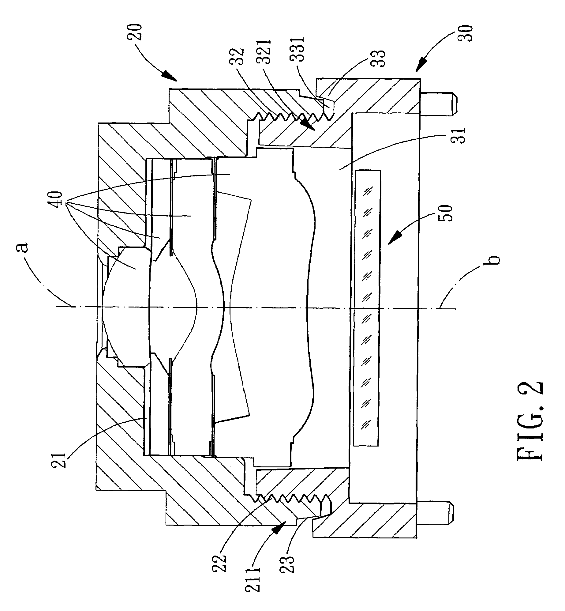
[0016]Referring to FIG. 2, a preferred embodiment of the present invention is shown and comprises a lens tube 20, a mounting base 30, a lens array 40 and an image sensor 50.

[0017]The lens tube 20 is a hollow cylindrical member having a receiving space 21, at the inner periphery of a flange 211 at the lower portion of the lens tube 20 is formed a locking portion 22, and on the outer periphery of the flange 211 is formed a first conical surface 23.

[0018]The mounting base 30 is interiorly formed with a receiving space 31, on an outer periphery of a flange 321 of the mounting base 30 are provided a locking portion 32 for mating with the locking portion 22 of the lens tube 20, and in the lower end of the flange 321 of the mounting base 30 is formed a concave portion 331. The concave portion 331 is formed with a second conical surface 33.

[0019]The lens array 40 is disposed in the receiving space 21 of the lens tube 20.

[0020]The image sensor 50 is disposed in the receiving space 31 of the ...


PUM


Abstract

A lens tube and a mounting base thereof comprise a lens tube for reception of a lens array and a mounting base for accommodation of an image sensor. On an outer periphery of the lens tube is formed a first conical surface, and in the mounting base is formed a concave portion. A second conical surface is formed in the concave portion for mating with the first conical surface of the lens tube. The first conical surface of the lens tube and the second conical surface of the mounting base can cooperate with each other, so as to prevent dust contamination and to make the central axis aligned with the optical axis.

Description

BACKGROUND OF THE INVENTION[0001]1. Field of the Invention[0002]The present invention relates to a lens tube and a mounting base thereof, wherein a first conical surface of the lens tube and a second conical surface of the mounting base cooperate with each other, so as to prevent dust contamination and to make the central axis aligned with the optical axis.[0003]2. Description of the Prior Art[0004]The existing lens tube 10 and the mounting base 11 thereof is shown in FIG. 1, in the lens tube 10 is formed a passage 12 in which being inserted a lens array 13, and the optical axis a of the lens array 13 is in alignment with the optical axis b of the passage 12. By such arrangements, the optical signal of the object to be shot will be focused on the image sensor 14 after passing through the lens array 13. In the passage 12 are formed a plurality of inner threads. In the mounting base 11 is defined a passage 12 and on the outer periphery of the passage 12 are formed a plurality of outer...

Claims


Application Information

Patent Timeline
Patent Type & Authority Patents(United States)
IPC IPC(8): G03B17/00F21V17/00G02B7/00
CPCG02B7/021G02B7/022H04N5/2254G03B3/00G03B17/28G02B13/0035H04N23/52H04N23/55
Inventor LI, MIN-CHE
Owner LARGAN PRECISION
Why Eureka
Try Eureka