Press apparatus

a technology of press and ejection device, which is applied in the direction of presses, ejection devices, manufacturing tools, etc., can solve the problems of increasing the number of maintenance times, increasing the number of movements of the apparatus, and increasing production time, so as to reduce the frequency of maintenance and improve production efficiency. , the effect of reducing the load on the apparatus

Active Publication Date: 2016-01-14
KEYLEX CORP
View PDF6 Cites 18 Cited by
  • Summary
  • Abstract
  • Description
  • Claims
  • Application Information

AI Technical Summary

Benefits of technology

[0007]In view of the foregoing background, it is therefore an object of the present invention to provide a press apparatus with high production efficiency and less chances of breakdown.
[0012]According to the first aspect of the invention, the upper die is fixed to the platform, and the machining die moves up and down with respect to the platform. This thus allows the machining die to machine the initially formed product, while keeping pressure-holding the initially formed product between the upper and lower dies, without the need to temporarily move up the platform as in Patent Document 1 in order to pressure-hold the product. This allows for improving production efficiency. Further, unlike Japanese Unexamined Patent Publication No. 2011-92946 having a complicated structure in which a support rod, a contact member, and a block are combined together, the structure of the present invention is a simple one with no such complicated structure. This prevents an excessive load from being applied to any specific part of the structure during the pressure holding of the product. As a result, breakdowns of the apparatus are avoidable, and therefore, the frequency of maintenance is reducible.
[0013]According to the second aspect of the invention, swing of the upper die, lower die, and machining die to be caused when pressing and machining the product is reduced. Thus, the load on the apparatus is further reduced compared to the first aspect of the invention, thereby preventing breakdowns of the apparatus. Further, the machining die is moved down while upward tension is being applied to the hydraulic press machines by the respective shock absorbers. This allows the machining die to move down when the hydraulic press machines have predetermined uniform hydraulic pressure, and hence allows the machining die to move down smoothly, thereby further reducing breakdowns of the apparatus.
[0014]According to the third aspect of the invention, while the outer peripheral portions of the initially formed product are being cut off by the trim dies moving down, the pierce die is simultaneously moved forward, thereby making a hole at an inner portion of the initially formed product. This means that the trimming and the piercing do not have to be performed independently, and the production time is therefore further reduced, compared to the first aspect of the invention. Further, it is not necessary to provide any drive source for moving the pierce die forward. It is thus possible to provide a low-cost apparatus.

Problems solved by technology

This increases the number of movements of the apparatus and, hence, the production time.
This may cause breakdowns more frequently in this portion, and cause an increase in the number of times of maintenance.

Method used


Image

  • Press apparatus
  • Press apparatus
  • Press apparatus

Examples


Embodiment Construction

[0020]Various embodiments of the present invention now will be described more fully hereinafter with reference to the accompanying drawings, in which some, but not all embodiments of the inventions are shown. Indeed, these inventions may be embodied in many different forms and should not be construed as limited to the embodiments set forth herein; rather, these embodiments are provided so that this disclosure will satisfy applicable legal requirements. The term “or” is used herein in both the alternative and conjunctive sense, unless otherwise indicated. The terms “illustrative” and “exemplary” are used to be examples with no indication of quality level. Like numbers refer to like elements throughout.

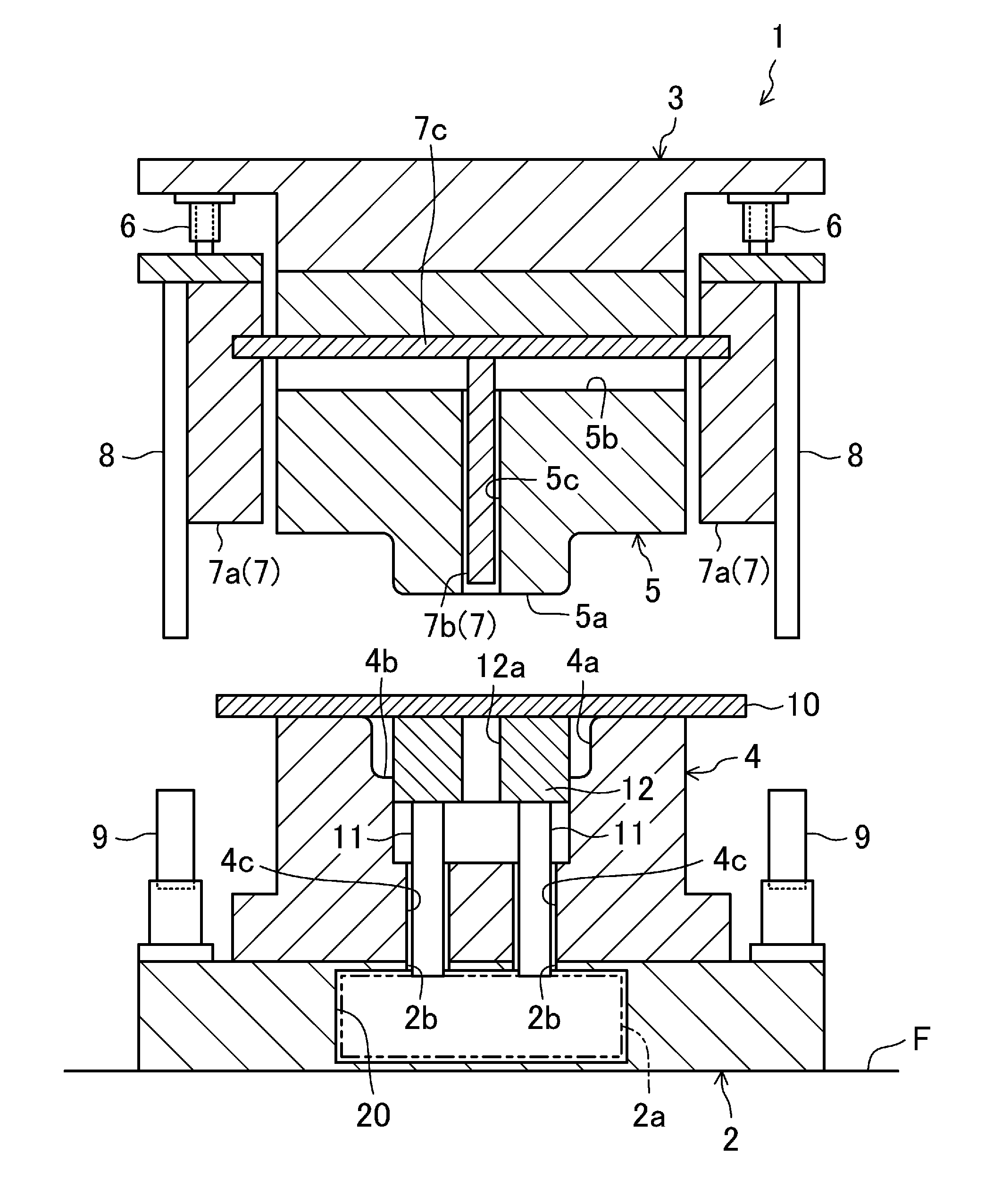
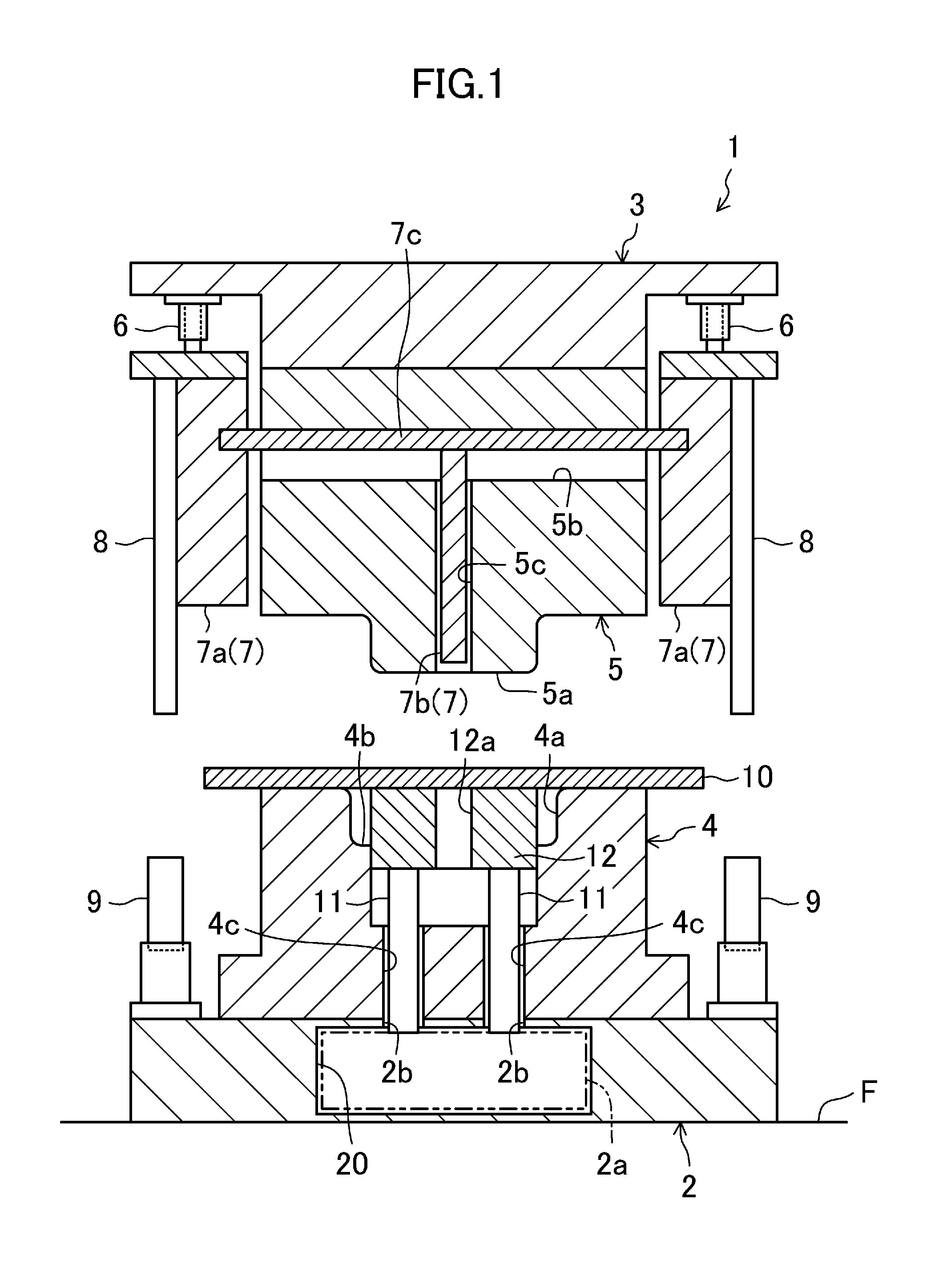
[0021]FIG. 1 illustrates a press apparatus 1 according to an embodiment of the present invention. The press apparatus 1 is intended to form a pressed product by a hot pressing method, and has a base 2 placed on the floor F, and a platform 3 arranged over the base 2 to move up and down u...


PUM

PropertyMeasurementUnit
pressureaaaaaaaaaa
tensile strengthaaaaaaaaaa
temperatureaaaaaaaaaa

Abstract

Provided is a press apparatus which ensures high production efficiency and has less chances of breakdown. Specifically, the press apparatus has a base placed on a floor, and a platform arranged over the base to face the base and move up and down. A lower die, on which a steel plate is to be placed, is fixed to the base. An upper die is fixed to the platform to press the plate against the lower die and turn it into an initially formed product through a downward movement of the platform, and to pressure-hold the initially formed product with the lower die. A machining die is supported on the platform to move up and down to machine the initially formed product and form a final product by moving down while pressure-holding the initially formed product.

Description

CROSS-REFERENCE TO RELATED APPLICATION[0001]This application is a continuation of and claims priority to and the benefit of International Application No. PCT / JP2013 / 002276, filed Apr. 2, 2013; the contents of which is hereby incorporated by reference in its entirety.BACKGROUNDRelated Field[0002]The present invention relates to a press apparatus in which a steel plate is pressed into an initially formed product, and the initially formed product is machined while it is being pressure-held in order to obtain a final product.[0003]Recently, in automobile industries, there is a growing demand for lightweight and high-safety vehicle body structures. To fulfill this demand, pressed products to form a vehicle body have been formed of a high tensile strength steel plate, or been formed by a hot-pressing method.[0004]For example, the press apparatus of Japanese Unexamined Patent Publication No. 2011-92946 (Paragraphs 0015-0029 and FIGS. 1-4)) forms a pressed product by a hot pressing method. ...

Claims


Application Information

Patent Timeline
Patent Type & Authority Applications(United States)
IPC IPC(8): B21D22/02
CPCB21D22/02B21D22/21B21D24/02B21D24/16B21D28/24B21D35/001B21D45/02B30B15/0076B21D24/06B21D24/12B21D24/14
Inventor ITAOKA, TSUYOSHITESHIMA, SHIGEKI
Owner KEYLEX CORP
Why Eureka
Try Eureka