Jack with selectively interchangeable components

a technology of components and jacks, applied in the field of hydraulic jacks, can solve the problems of user's inability to find out too late, the point of lift may shift from one point, and the user's inability to adjust the jack, so as to reduce the wobble of the jack, add lateral stability, and add stability

Active Publication Date: 2011-05-05
ALLTRADE TOOLS
View PDF6 Cites 17 Cited by
  • Summary
  • Abstract
  • Description
  • Claims
  • Application Information

AI Technical Summary

Benefits of technology

[0008]The present invention is a novel and unique kit of components that extends the useful range operation of a hydraulic jack so that it is able to perform the functions that are typically required to be performed by more than one hydraulic jack. The invention also includes a novel feature for stabilizing a jack to elevate a load completely off the ground, with no portion of the load remaining on the ground.
[0010]In a preferred embodiment, each side arm defines an opening configured to allow the handle to be snugly passed through both openings at the same time. This arrangement provides for added stability when the jack is being used to elevate a load entirely, with no portion of the load remaining on the floor.
[0013]The arrangement thus described permits the user to use the first platform alone to elevate loads entirely, so that no portion of the load remains on the floor. Such loads might be smaller vehicles such as motor bikes and snowmobiles. Optionally, the user may insert the handle used to actuate the jack into openings on either side of the jack in order to provide added stability to the jack under this load condition.
[0016]Thus, the invention allows up to three potential lifting capabilities to be provided by one jack, in addition to added lateral stability derived from components of the jack that are necessarily present for operation of the jack. Thus, no additional material is required to create this additional stability, and the only additional fabrication needed is to cut two openings in the sides of the jack.
[0017]In a further aspect of the invention, the handle, when passed through the openings, includes a fixed ridge at one end of the handle and a movable ridge at an opposite end of the handle, each ridge being configured to reduce wobble of the jack on a floor surface. Preferably, the movable ridge comprises a cylindrical portion slidable over the handle, and an annular portion protruding outwardly from the cylindrical portion.
[0018]In another aspect of the invention, the second magnitude (of the second platform) is less than twenty percent the first magnitude (of the first platform). This allows the second platform, when present, to assume all the load when elevating a motor car, with reduced likelihood of a portion of the car undercarriage contacting the first platform. To further reduce this likelihood, the second platform preferably has an aspect ratio of one, and no horizontal dimension of the second platform exceeds six inches. Furthermore, the second platform is preferably positioned above the first platform by at least one inch in order to increase clearance of the load undercarriage from the first platform.

Problems solved by technology

However, the undercarriage of a motor vehicle typically has a complex shape so that, if a multiple point ram were used to elevate the vehicle, or if a large flat plate were used on the end of the ram, it is likely that the point of lift may shift from one point to another as the vehicle is elevated.
This is highly undesirable because the user may not know which point on the underside of the vehicle will eventually be the point of load when the vehicle is fully elevated.
Thus, the user may find out too late that an inappropriate point on the underside of the vehicle has become the point of load.
The point at which load is applied may be inappropriate because it may buckle, or even worse, may break.
For example, a user will try to avoid applying a point of hydraulic lift to a flat floor panel of the motor vehicle because the floor panel may bend out of plane or may be punctured by the hydraulic lift.
However, where the jack is the only point of support for the vehicle, there is always an increased risk that the jack itself may tipple over, with disastrous consequences.
However, this solution results in a hydraulic jack that occupies a very large area “footprint,” which may add to the overcrowding of a small workshop.
The reason that the load is taken by the wheels in this design and not by a central platform to the undercarriage, is that the wheel base of such vehicles may be so short that, when fully lifted in front about the pivoting back wheels, the vehicle slopes upward at a considerable angle.
This would tend to create a dangerous situation if the lifting were caused by a load applied to the undercarriage because the point of contact will substantially realign itself from horizontal as the vehicle is elevated, producing the possible very undesirable result that the jack slips out of engagement with the tractor.
A noticeable problem that has arisen in the art is that many workshops, both commercial and private, may be required to possess all three types of hydraulic jack described above to deal with the various types of vehicle that must be serviced.
This gives rise to issues of financial expense, and also to issues of overcrowding and storage in the workshop for a host of different hydraulic jacks.
Moreover, even where all three types of jack are provided in a workshop, the kind that elevates a vehicle entirely off the floor always suffers the risk of instability for which no suitable solution is available.

Method used


Image

  • Jack with selectively interchangeable components
  • Jack with selectively interchangeable components
  • Jack with selectively interchangeable components

Examples


Embodiment Construction

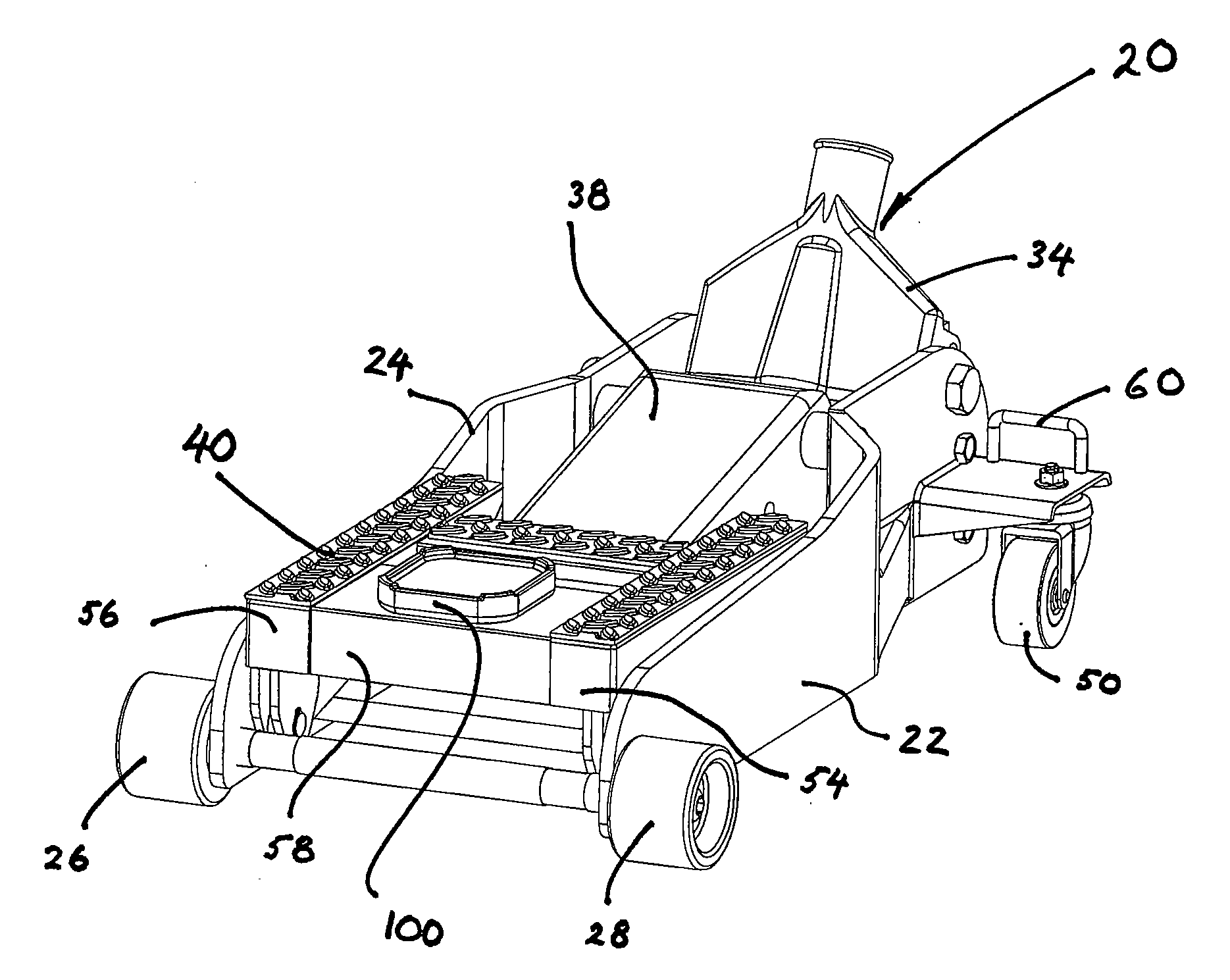
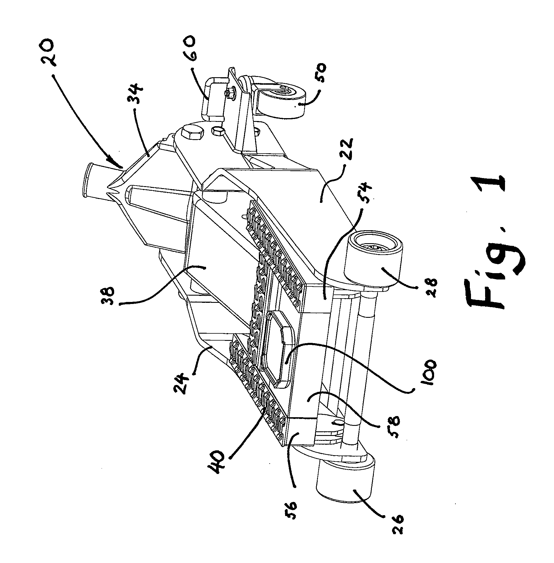
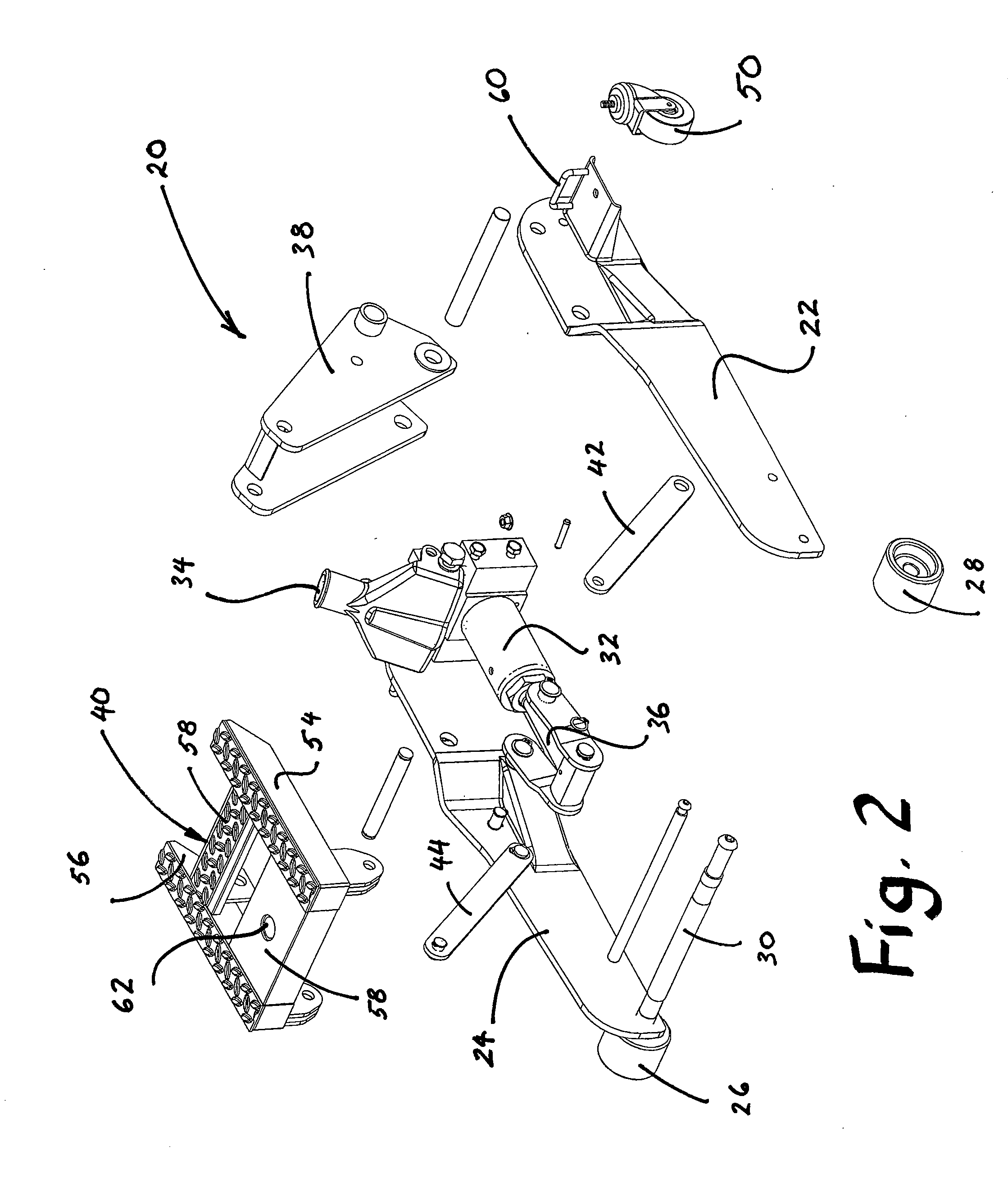
[0029]With reference to the figures, which are shown by way of exemplification and not limitation, a modular hydraulic jack having features of the present invention is described. The present invention initially comprises a specialized lifting jack 20 specially configured for use in combination with other components, under a variety of load and stability conditions.

[0030]The specialized jack 20 of the present invention may be seen as one of the invention components in each of FIGS. 1-9. Initially, FIG. 2 shows the specialized jack 20 in an exploded view as comprising two opposing left and right outer side arms 22, 24 extending from the front end to the back end of the jack. At the front of the side arms, two front wheels 26, 28 are situated and connected to each other by an axle 30 which also serves to stiffen the jack. Two rear wheels 50 (only one rear wheel visible in the figures) are situated at the rear end of the jack, capable of swiveling independently of each other for providi...


PUM


Abstract

A novel hydraulic jack kit is disclosed comprising a specialized jack configured to be compatible with selectively interchangeable components. The specialized jack on its own is configured to lift vehicles such as motorbikes and snowmobiles completely off the floor, so that the only support is the jack itself. The specialized jack is also configured to receive a platform component that converts the jack into one suitable for lifting automobiles with a large wheel base that will have two wheels remaining on the floor when lifted. It is further configured to receive a platform component that converts the jack into one suitable for lifting a vehicle with a short wheel base, where the elevated vehicle adopts a large angle of elevation. In all configurations, a novel stabilizing structure is provided.

Description

BACKGROUND[0001]The present invention relates to hydraulic jacks for lifting loads such as motorized vehicles and other heavy objects and equipment. Specifically, the invention relates to a versatile modular hydraulic floor jack adapted to lift different types of vehicular load, while being configured at the same time to provide enhanced lateral stability.[0002]Hydraulic floor jacks are known in the art. Typically, a hydraulic floor jack includes a hydraulic ram that is given a mechanical advantage by known means, namely, in which a hydraulic press is harnessed to convert a manual input force into an output force delivered by a piston, the output force being considerably magnified over the input force. The magnified piston force may be applied directly to elevate a load, or it may be utilized to pivot an elevation arm of the floor jack, which elevates the load in a pivoting action.[0003]A number of different types of floor jack have been developed, each for a specialized purpose. Fo...

Claims


Application Information

Patent Timeline
Patent Type & Authority Applications(United States)
IPC IPC(8): B66F5/04B66F3/36
CPCB66F5/04
Inventor HERNANDEZ, HECTOR R.
Owner ALLTRADE TOOLS
Why Eureka
Try Eureka