Soap holding device having design imprinter

a technology of holding device and soap, which is applied in the direction of dispensers, dough shaping, manufacturing tools, etc., can solve the problems of gelatinous condition, large portion of the underside of the soap being left in a sticky condition, and affecting the effect of soap drying, deep cleansing, and good skin exfoliation

Active Publication Date: 2010-09-07
LENARD MARK B
View PDF2 Cites 16 Cited by
  • Summary
  • Abstract
  • Description
  • Claims
  • Application Information

AI Technical Summary

Benefits of technology

[0018]It is another object of the present invention to provide an improved soap holding device which scores or texturizes the surfaces of the soap bar with an impression so as to produce the capability of better skin exfoliation and deep cleansing due to both sides of the soap bar being scored or roughed up.
[0019]It is still another object of the present invention to provide an improved soap holding device which allows for the drying of a relatively larger surface area on the soap.
[0020]It is still yet another object of the present invention to provide an improved soap holding device which is cost effective to manufacture and which is relatively easy and non-problematic to use in operation.
[0021]In a preferred embodiment of the present invention, there is provided a soap holding device which allows for imprinting, scoring and expedient drying of a soap bar. The soap holding device includes a base member having a first grid pattern with a plurality of apertures and a cover member having the capability of being telescopically pressed downwardly into the base member as the soap becomes smaller with use in order to provide continual scoring and imprinting. The cover member also includes a second grid pattern with a plurality of apertures and an imprinting portion for imprinting designs onto the soap bar after every use.

Problems solved by technology

Since the advent of soap holders, users have noticed that when the underside of a bar of soap is not thoroughly dried in the holder the soap becomes sticky, adheres to the bottom of the holder and is repulsive to the touch.
However, these attempts still result in having a substantial portion of the underside of the soap being left in a sticky, gelatinous condition.
However, after just a couple of uses of the soap, the imprint dissolves into the bar leaving a smooth surface without an imprint.
When the user places the imprint-side of the soap facing the bottom of the holder, the imprint dissolves even quicker because the imprint becomes sticky and gelatinous due to inadequate drying.

Method used


Image

  • Soap holding device having design imprinter
  • Soap holding device having design imprinter
  • Soap holding device having design imprinter

Examples


Embodiment Construction

[0031]It is to be distinctly understood at the outset that the present invention shown in the drawings and described in detail in conjunction with the preferred embodiments is not intended to serve as a limitation upon the scope or teachings thereof, but is to be considered merely as an exemplification of the principles of the present invention.

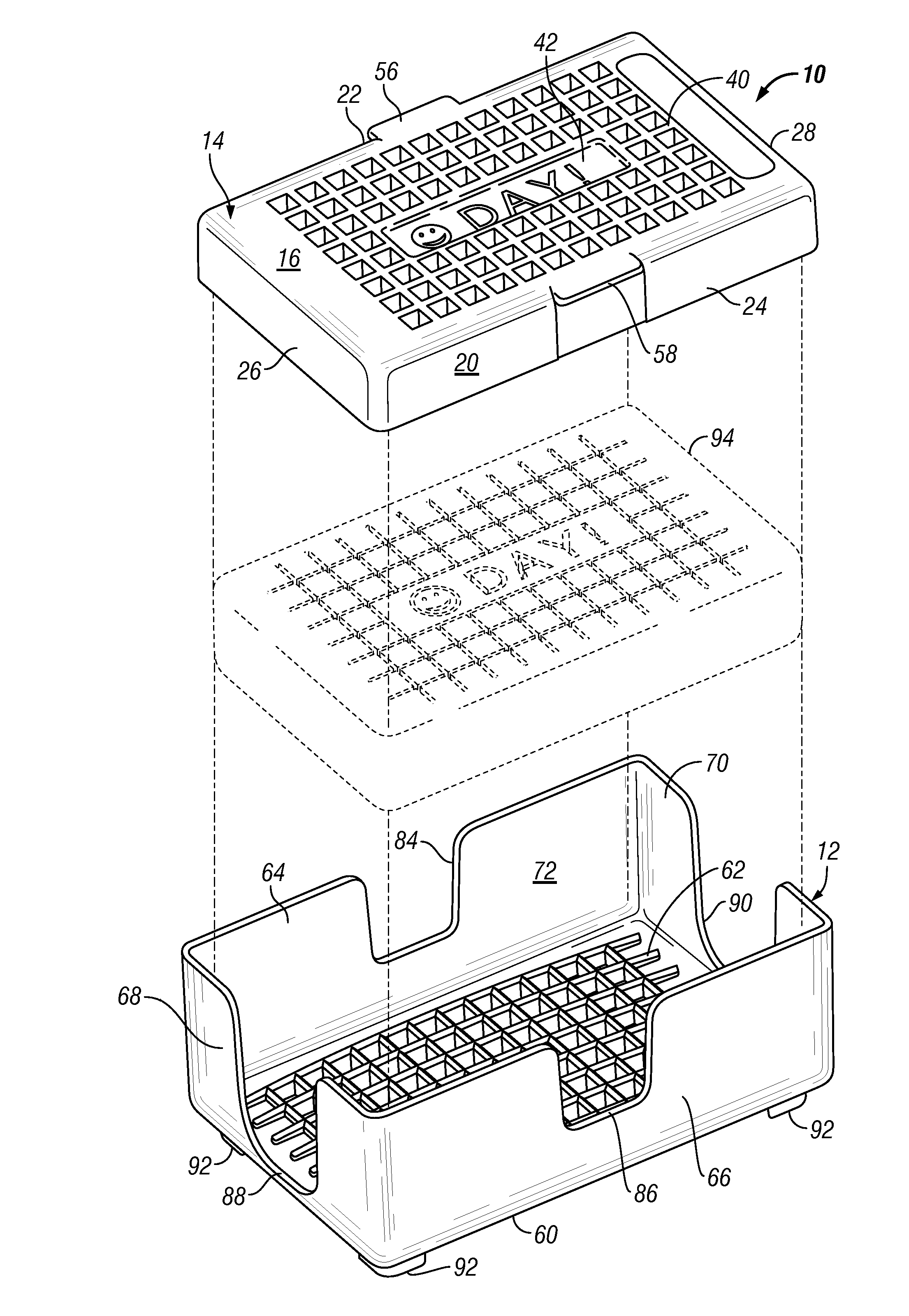
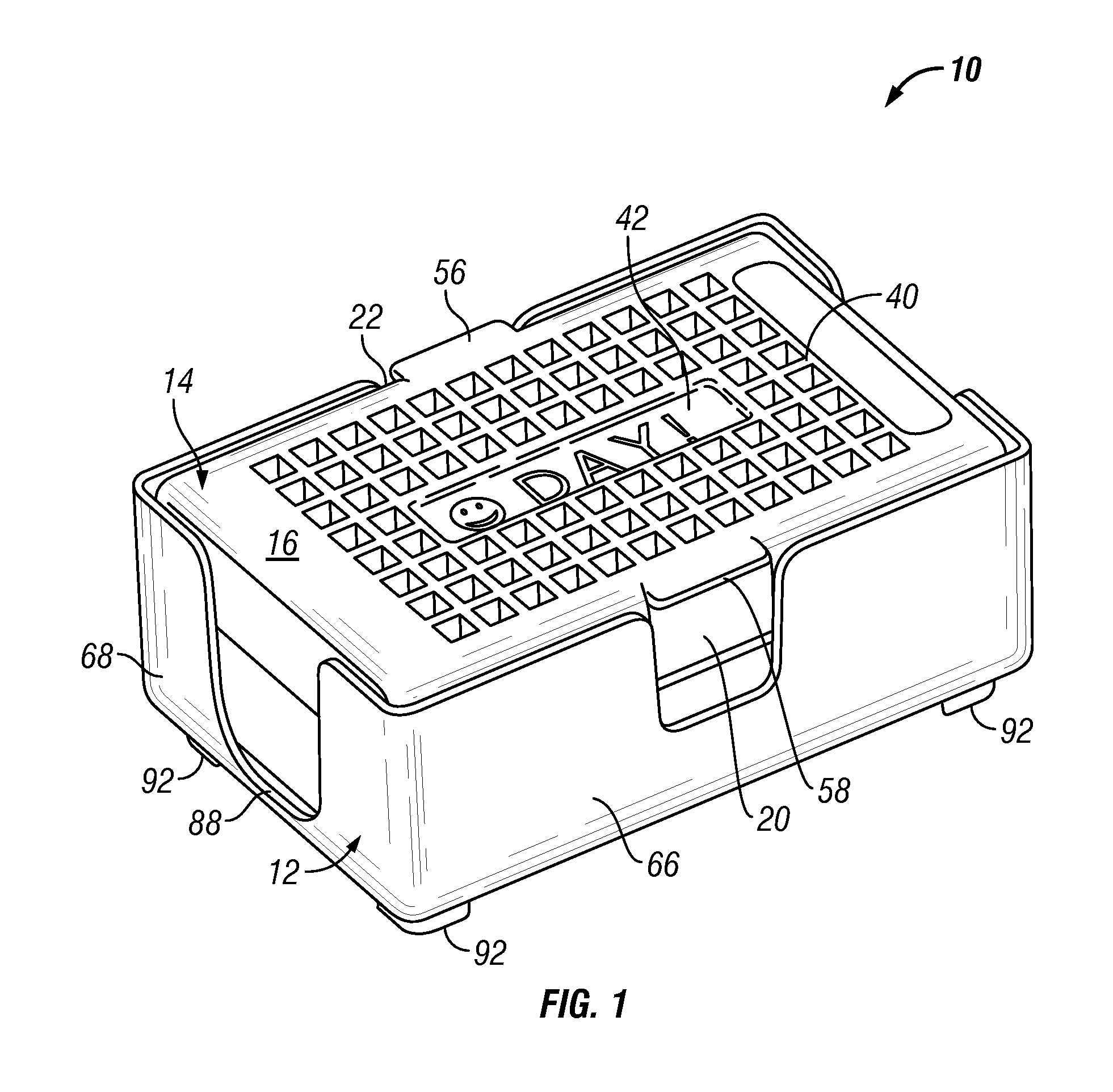
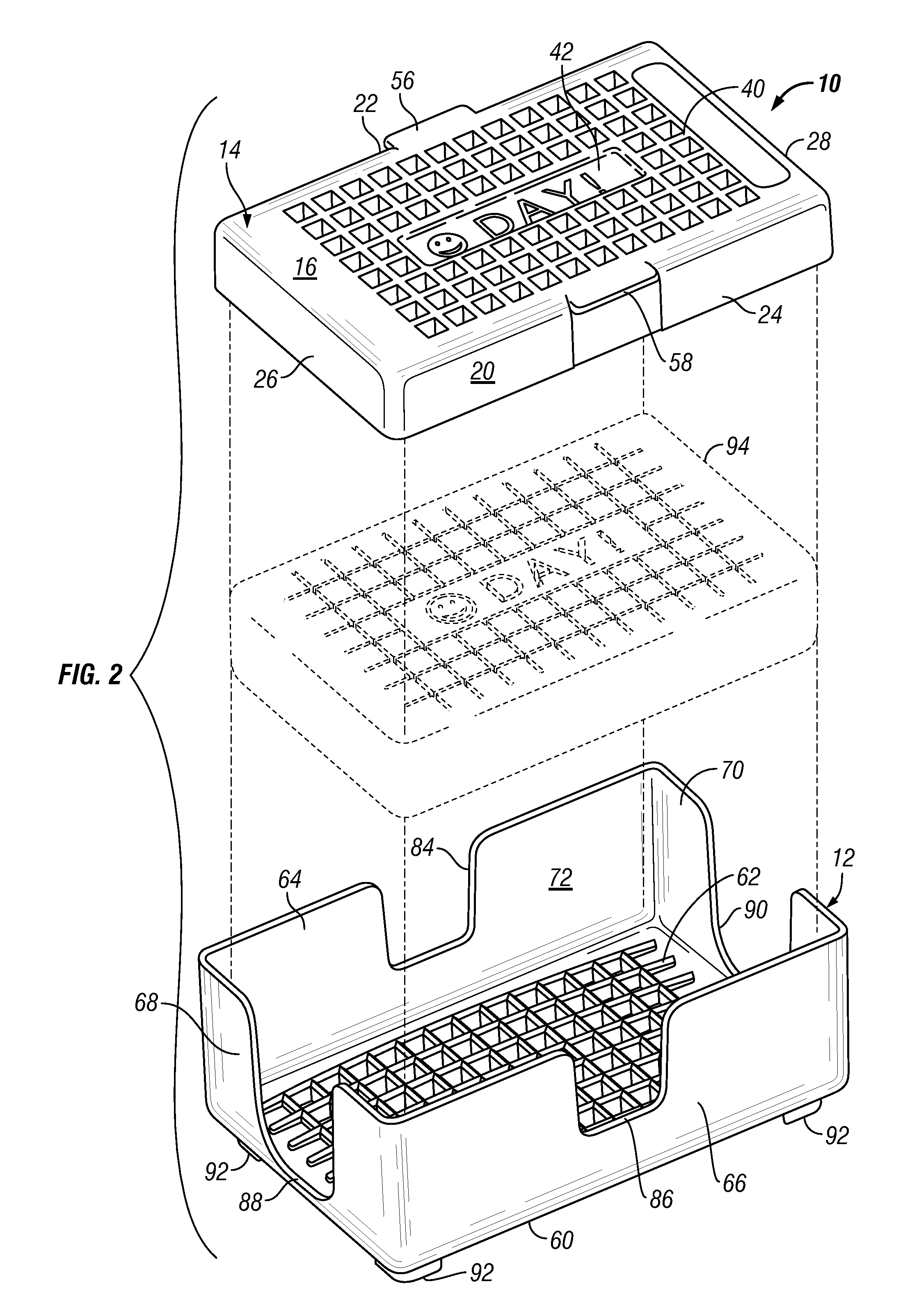
[0032]Referring now in detail to the drawings, wherein like reference characters designate like or corresponding parts throughout the several views, there is illustrated in FIGS. 1 through 8 an improved soap holding device 10 constructed in accordance with the principles of the present invention.

[0033]As shown in FIGS. 1 and 2, there is provided a soap holding device 10 which is defined by a base member 12 and a co-mating cover or lid member 14. The soap holding device 10 may be fabricated from plastic or any other similar formable material. The cover member 14 is designed to seat within and to be telescopically pressed downwardly into base m...


PUM

PropertyMeasurementUnit
pressureaaaaaaaaaa
shapeaaaaaaaaaa
surface areaaaaaaaaaaa

Abstract

A soap holding device includes a base member having a first grid pattern with a plurality of apertures and a co-mating cover member having the capability of being lowered telescopically downwardly into the base member as a soap bar becomes smaller with use. The cover member also includes a second grid pattern with a plurality of apertures and an imprinting portion for imprinting designs onto the soap bar after every use when the cover member exerts pressure thereon to produce the capability of better skin exfoliation and deep cleansing.

Description

BACKGROUND OF THE INVENTION[0001]1. Field of the Invention[0002]This invention relates generally to soap holding devices, and more particularly, the present invention relates to an improved soap holding device formed of a base member and a co-mating cover or lid member. The cover member includes one grid-like pattern and a design both of which will be imprinted onto the soap after every use when the cover member is telescopically pressed downwardly into the base member. The base member includes another grid-like pattern that will also be imprinted onto the soap after every use.[0003]2. Description of the Prior Art[0004]Since the advent of soap holders, users have noticed that when the underside of a bar of soap is not thoroughly dried in the holder the soap becomes sticky, adheres to the bottom of the holder and is repulsive to the touch. As a result, many designs of soap holders have been attempted to resolve this inconvenience. Numerous designs have incorporated a limited number o...

Claims


Application Information

Patent Timeline
Patent Type & Authority Patents(United States)
IPC IPC(8): B29C59/00B28B3/00B29C43/54
CPCA47K5/09
Inventor LENARD, MARK B.
Owner LENARD MARK B
Why Eureka
Try Eureka