
Compact vibrator and seismic monitoring or prospecting method using such a vibrator

a compact, vibrator technology, applied in the direction of generator/motor, measurement device, instruments, etc., can solve the problems of unstable vibrator, unable to work on even slightly sloping ground, and ceramic pillars of great length becoming more fragil

Inactive Publication Date: 2002-01-15
GAZ DE FRANCE +2
View PDF5 Cites 21 Cited by
  • Summary
  • Abstract
  • Description
  • Claims
  • Application Information

AI Technical Summary

Benefits of technology

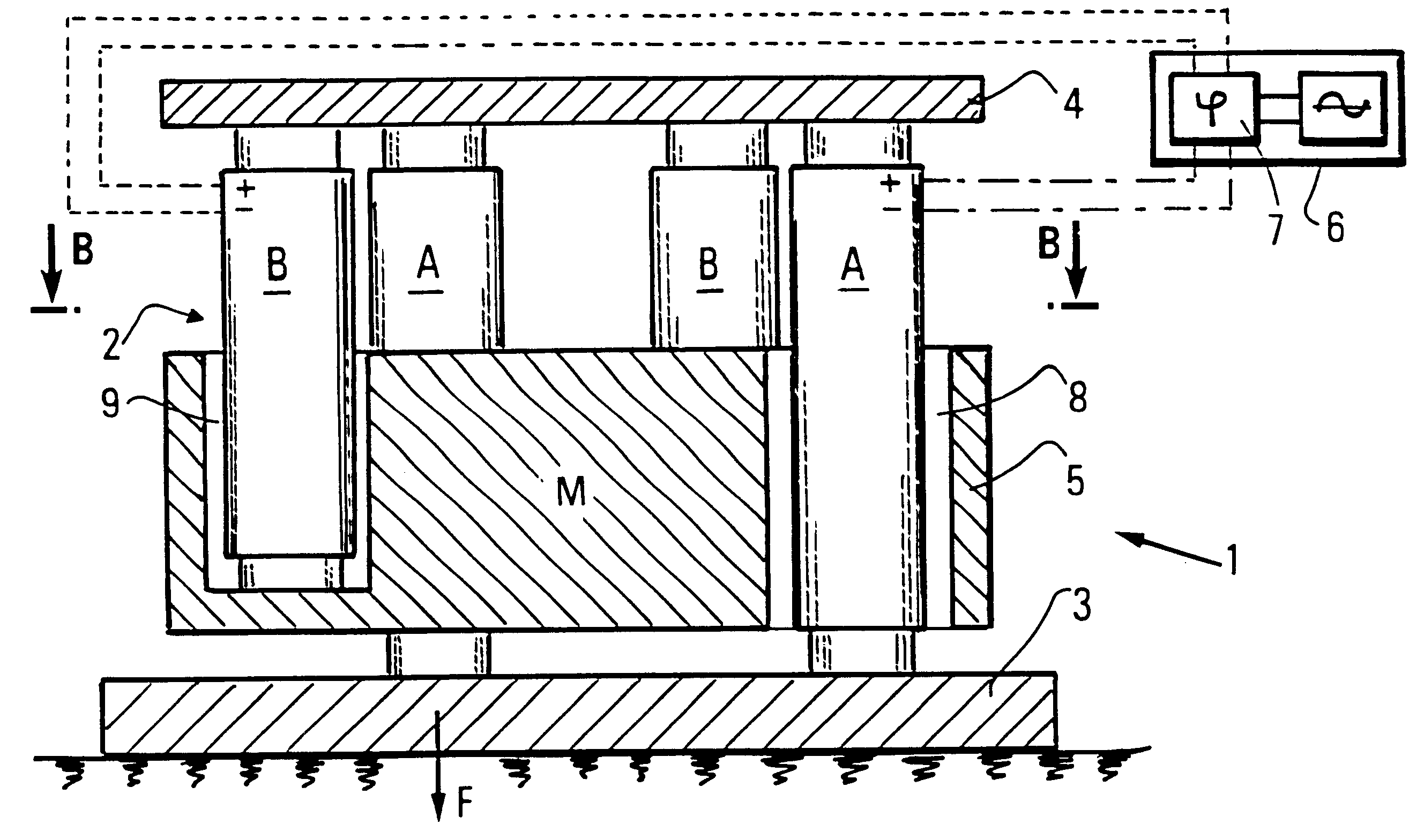
With such a layout of at least one pair of electromechanical transducers with motive elements of limited length, coupled and combined by means of one or more relay plates, the inertia mass can be positioned next to the baseplate, which allows obtaining of a very robust and very stable vibrator of limited overall height.
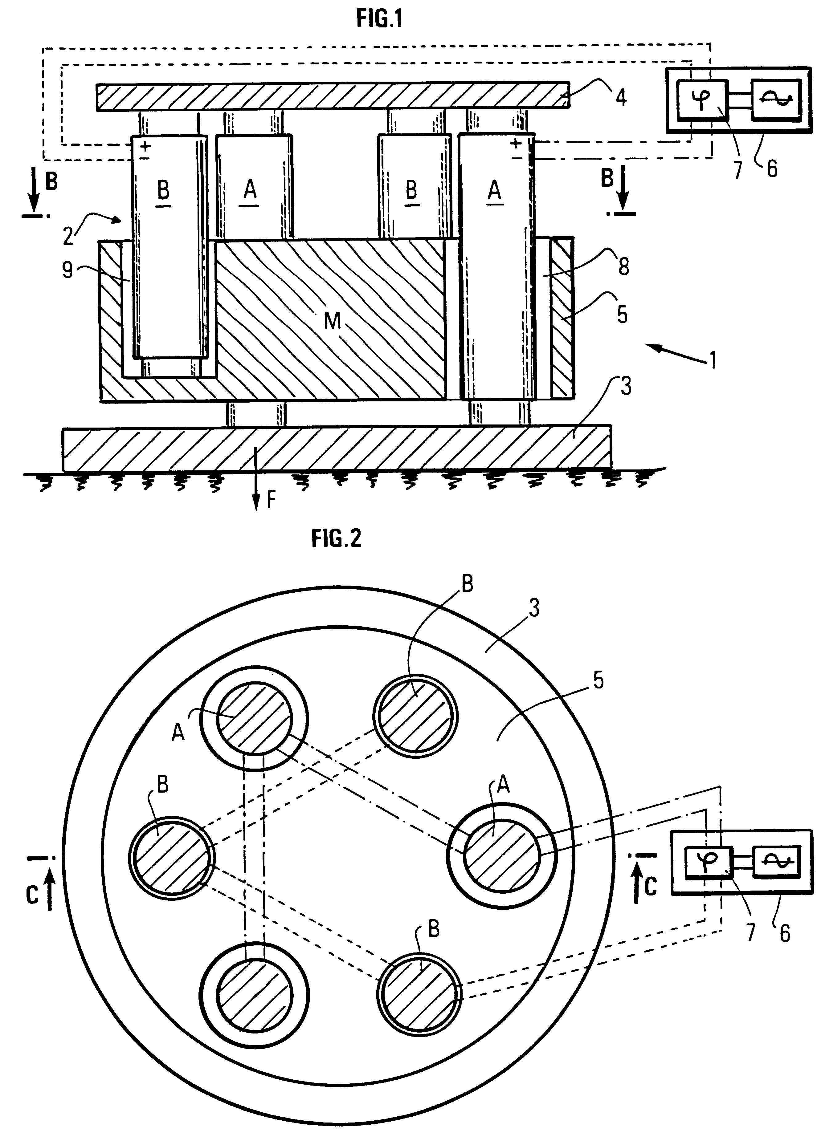
According to a preferred embodiment, the size of the vibrator is decreased by making one or more recesses through the inertia mass through which run the motive elements of each transducer.
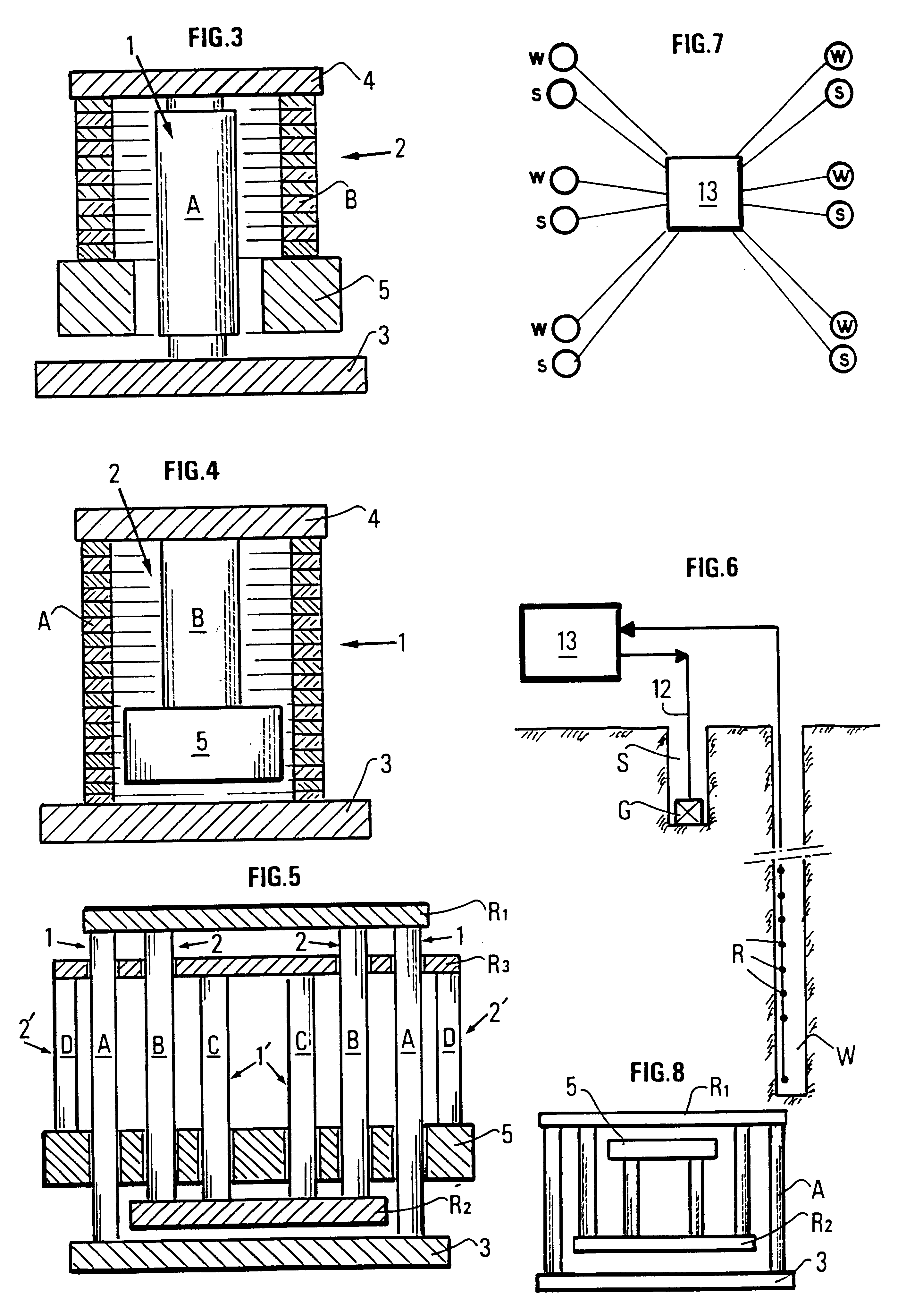
As a result of the robustness and compactness thereof, the vibrator according to the invention can be readily installed permanently in a cavity provided in the ground and intermittently excited by means of the network, within the scope of periodic underground zone monitoring operations, or it can be used for seismic prospecting operations.

Problems solved by technology

As a result of this piling, the heavy inertia mass is placed relatively high so that the vibrator is unstable and ill-suited for working on an even slightly sloping ground without previous anchoring.
Furthermore, ceramic pillars of great length prove to be more fragile.

Method used


Image

  • Compact vibrator and seismic monitoring or prospecting method using such a vibrator
  • Compact vibrator and seismic monitoring or prospecting method using such a vibrator
  • Compact vibrator and seismic monitoring or prospecting method using such a vibrator

Examples


Embodiment Construction

The vibrator V according to the invention is made by mechanical coupling of transducers each comprising pillars each, as it is known in the art, including piles of sensitive elements electrically connected in series, of, for example, a piezoelectric type.

The embodiment of FIGS. 1, 2 comprises two transducers 1 and 2 connected in opposition, each including pillars of piled disks. A first end of each pillar A of a first piezoelectric transducer 1 is tightly fastened to a baseplate 3 suited to be pressed against the ground surface or the bottom of a hole. At the opposite end thereof, pillars A are tightly fastened to a relay plate 4. Each pillar B of a second piezoelectric transducer 2 is tightly fastened, at a first end, to relay plate 4 and, at the opposite end thereof, to a sufficiently heavy inertia mass 5. The layout is such that inertia mass 5 is suspended from relay plate 4 by pillars B of a second piezoelectric transducer 2, relay plate 4 itself being supported by pillars A res...


PUM


Abstract

Compact vibrator for emitting elastic waves in a material medium such as the subsoil. The vibrator comprises a baseplate (3) intended to be coupled in operation with a surface of this medium, an inertia mass (5) and at least a pair of electromechanical transducers (1, 2) comprising each one or more pillars (A, B) made for example of a piezoelectric or magnetostrictive material. Pillars (A) of first transducer (1) are interposed between baseplate (3) and a relay plate (4). Pillars (B) of the second transducer are interposed between relay plate (4) and inertia mass (5), on the same side of relay plate (4) as pillars (A) preferably, so that inertia mass (5) is positioned in the vicinity of baseplate (3), which contributes to the compactness and to the stability of the vibrator that can therefore be used on slightly sloping surfaces. An excitation generator (6) comprising phase shifting means (7) respectively applies to transducers (A, B) phase-shifted signals that are amplitude-modulable, so that their vibrations combine. The vibrator can be applied: notably for equipping an underground zone under development with periodic seismic monitoring means or for carrying out seismic prospecting operations.

Description

1. Field of the InventionThe present invention relates to a compact electromechanical vibrator and to an implementation method.2. Description of the Prior ArtElectromechanical vibrators find applications notably within the scope of seismic exploration operations where seismic images of an underground formation to be explored are formed from elastic waves picked up by suitable seismic receivers, these waves being reflected by the subsoil discontinuities in response to waves emitted by a source, either an impulsive source: charge of explosives in a hole, air guns towed by a boat at sea, etc., or vibrators emitting variable-duration signals, generally with a variable frequency. The frequency variation can be continuous within a certain frequency range (sweep) as described in U.S. Pat. No. 2,688,124 or discontinuous with binary coding as in French patent 2,589,587.The vibrators can be electromagnetic, electro-hydraulic or piezoelectric type vibrators. A piezoelectric type vibrator gener...

Claims


Application Information

Patent Timeline
IPC IPC(8): G01V1/02G01V1/143
CPCG01V1/143
Inventor MEYNIER, PATRICK
Owner GAZ DE FRANCE
Learn More