Hydraulic shock absorber

a technology of shock absorber and shock absorber, which is applied in the direction of shock absorbers, vibration dampers, springs/dampers, etc., can solve the problems of design of the top surface of the cap that tends to get into a rut, and adversely affects the interference of the vehicle body side such as the handle, cowl and the lik

Active Publication Date: 2012-08-07
HITACHI ASTEMO LTD
View PDF25 Cites 21 Cited by
  • Summary
  • Abstract
  • Description
  • Claims
  • Application Information

AI Technical Summary

Benefits of technology

[0006]An object of the present invention is to provide a hydraulic shock absorber provided with a plurality of adjusting portions in a cap of a vehicle body side tube, in which a height is restricted and the outer appearance becomes streamlined.

Problems solved by technology

Accordingly, it is necessary that the adjusting portions are provided in such a manner that operation portions thereof are shifted from each other in an axial direction (a height direction), it is unavoidable to make a height of the adjusting portions in a center side higher, thereby adversely affecting an interference with a vehicle body side such as a handle, a cowl and the like.
Further, a design of a top surface of the cap tends to get into a rut.

Method used


Image

  • Hydraulic shock absorber
  • Hydraulic shock absorber
  • Hydraulic shock absorber

Examples


Embodiment Construction

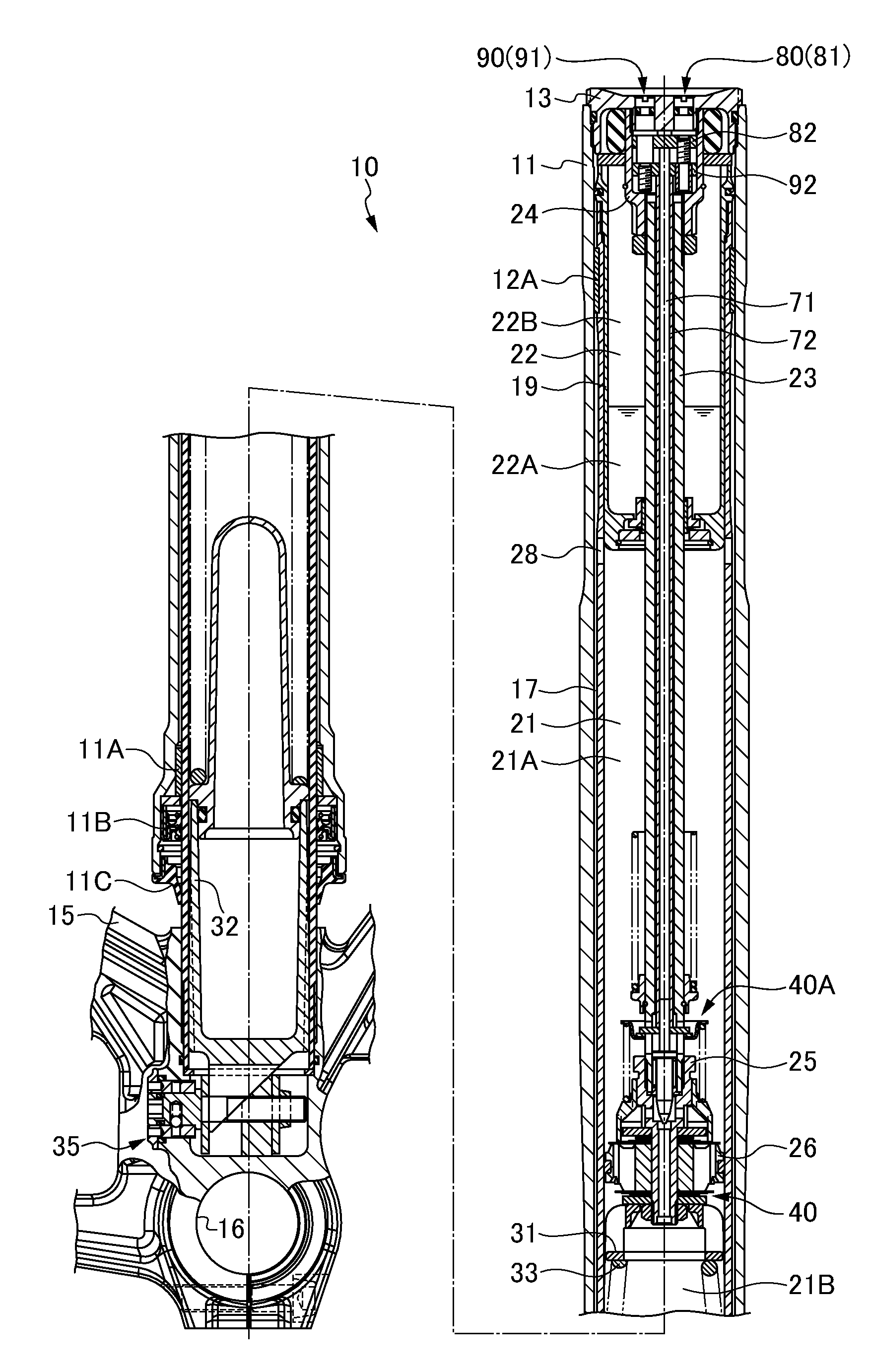
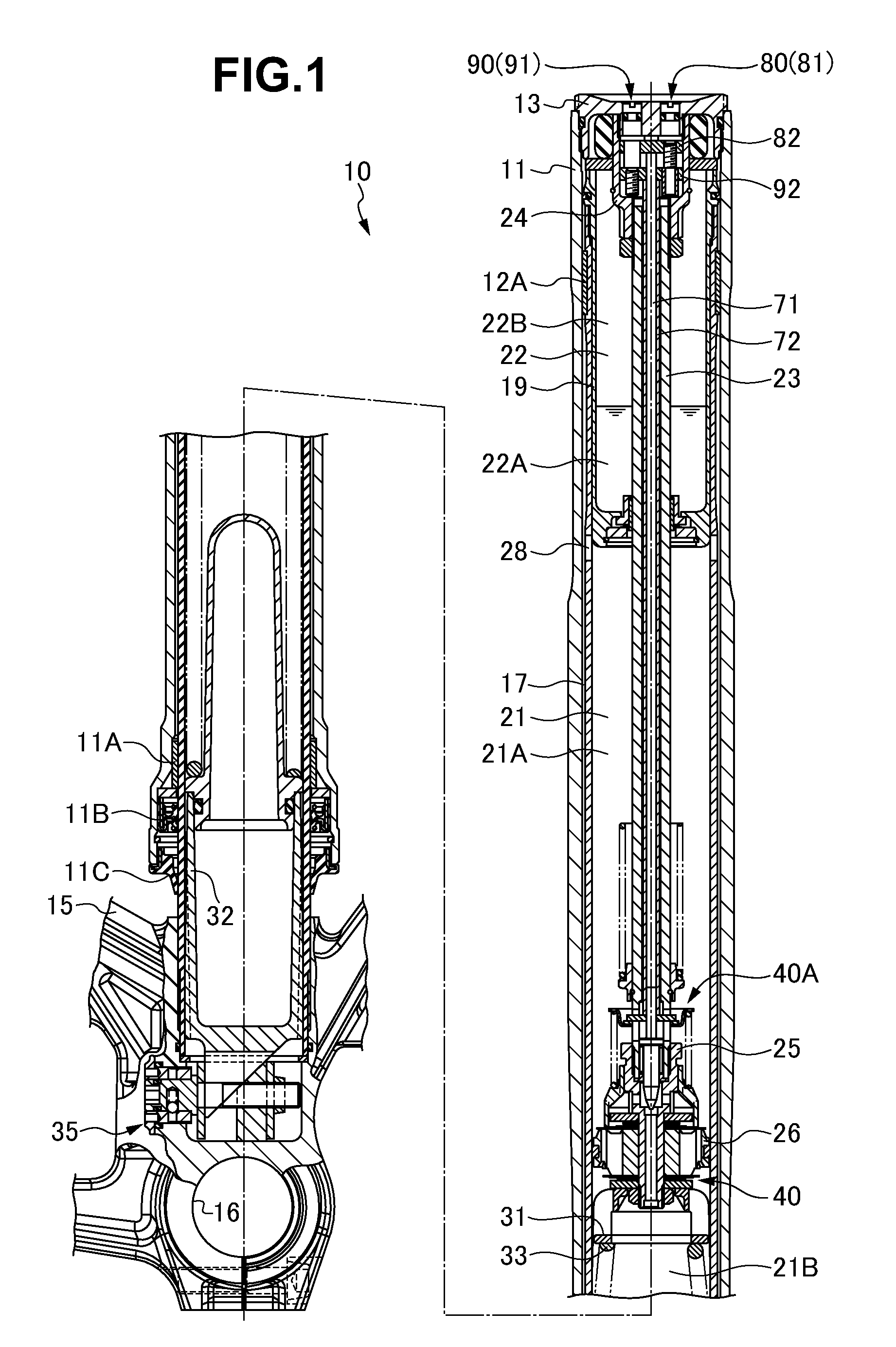
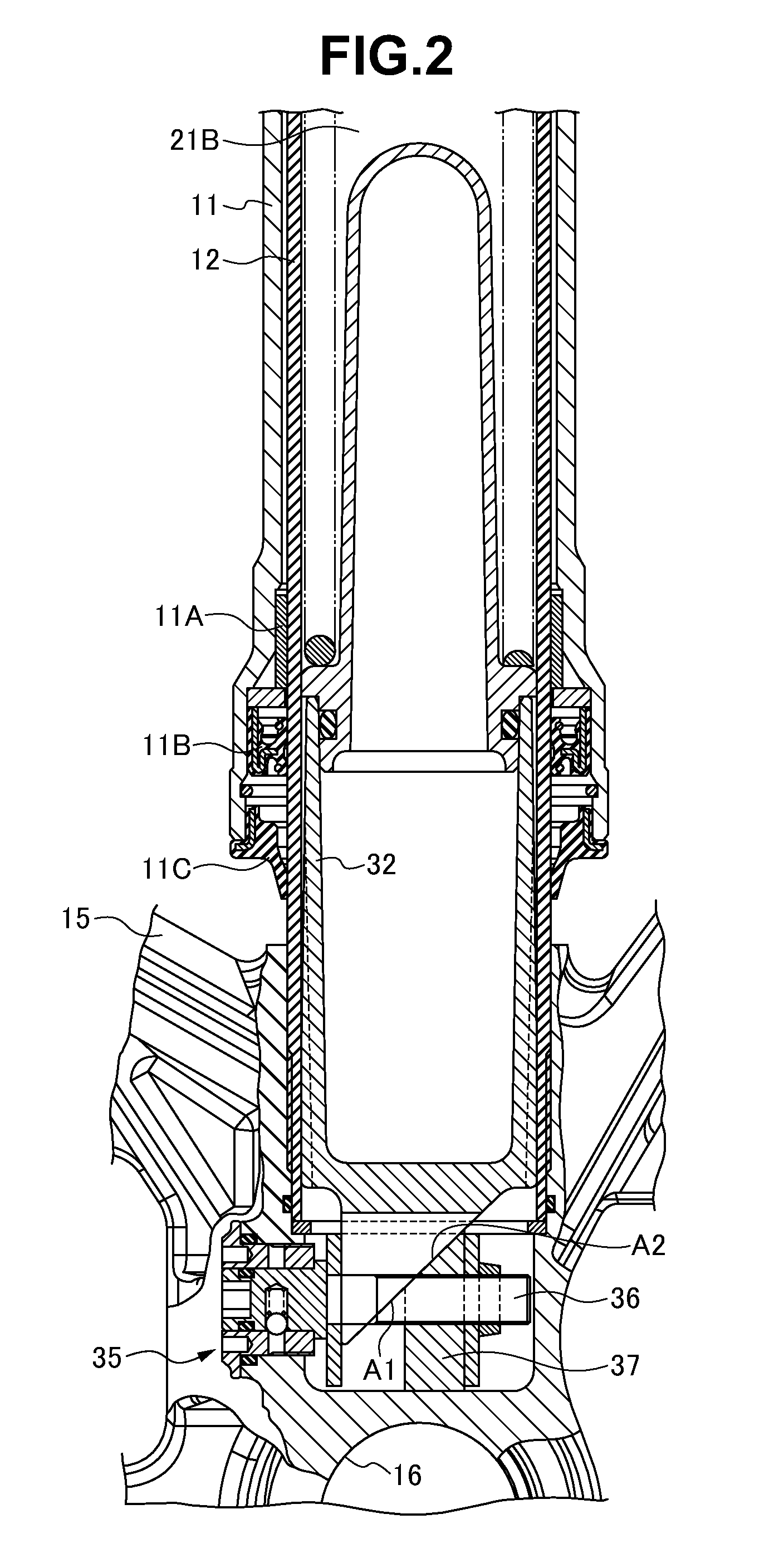
[0020]A front fork (a hydraulic shock absorber) 10 is constituted by an inverted type front fork in which an outer tube 11 is arranged in a vehicle body side, and a inner tube 12 is arranged in a wheel side. As shown in FIGS. 1 to 4, the inner tube 12 is slidably inserted to an inner portion of the outer tube 11 via a guide bush 11A fixed to an inner periphery of a lower end opening portion of the outer tube 11 and a guide bush 12A fixed to an outer periphery of an upper end opening portion of the inner tube 12. Reference symbol 11B denotes an oil seal, and reference symbol 11C denotes a dust seal. A cap 13 is screwed in a liquid tight manner to the upper end opening portion of the outer tube 11 so as to be sealed, and a vehicle body side attaching member is provided in an outer periphery of the outer tube 11. An axle bracket 15 is inserted and attached in a liquid tight manner to the lower end opening portion of the inner tube 12 so as to be screwed and construct a bottom portion o...


PUM


Abstract

In a hydraulic shock absorber structured such that a vehicle body side tube and an axle side tube are slidably fitted, and a plurality of adjusting portions are provided in a cap sealed to an upper end opening portion of the vehicle body side tube, a plurality of adjusting portions are arranged side by side in a plan view of the cap.

Description

BACKGROUND OF THE INVENTION[0001]1. Field of the Invention[0002]The present invention relates to a hydraulic shock absorber of a front fork and the like. More specifically, the invention relates to a hydraulic shock absorber with a reduced adjusting portion height and or a streamlined appearance.[0003]2. Description of the Related Art[0004]In a front fork (a hydraulic shock absorber) for a motor cycle, as described in Japanese Patent Application Laid-Open (JP-A) No. 2007-225066 (patent document 1), a plurality of adjusting portions for adjusting a damping force are provided in a cap which is structured such that a vehicle body side tube and an axle side tube are slidably fitted, and is sealed to an upper end opening portion of the vehicle body side tube.[0005]In the conventional front fork, a plurality of adjusting portions are coaxially arranged in a plan view of the cap. Accordingly, it is necessary that the adjusting portions are provided in such a manner that operation portions ...

Claims


Application Information

Patent Timeline
Patent Type & Authority Patents(United States)
IPC IPC(8): F16F9/48
CPCF16F9/462F16F9/466
Inventor MURAKAMI, YOSUKE
Owner HITACHI ASTEMO LTD
Why Eureka
Try Eureka