
Method and apparatus for pulsed harmonic ultraviolet lasers

a pulsed harmonic and ultraviolet laser technology, applied in the direction of optical resonator shape and construction, instruments, optics, etc., can solve the problems of requiring fast optomechanical control and extreme measures, significant engineering challenges, and extraordinarily difficult engineering, so as to increase the output of duv, increase the operating life and reliability, and facilitate manufacturing operations

Active Publication Date: 2010-12-14
LADARSYST INC
View PDF14 Cites 16 Cited by
  • Summary
  • Abstract
  • Description
  • Claims
  • Application Information

AI Technical Summary

Benefits of technology

"The present invention relates to a laser apparatus that produces coherent pulsed ultraviolet light with pulse durations ranging from 1 ps to 1 μs and 10 million or more pulses per second. The apparatus includes one or more source lasers that emit visible to near-infrared light and uses FC stages to convert a portion of the light from the source laser(s) into UV radiation. The nonlinear FC device used in the apparatus includes a huntite-type aluminum double borate material that has a composition given by RAl3B4O12. The apparatus can be used in various applications such as industrial laser machining, optical communication, and biological research."

Problems solved by technology

Such cavities pose significant engineering challenges, requiring fast opto-mechanical control and extreme measures to fight thermal and vibrational noise.
The engineering is extraordinarily difficult when consecutive resonant cavities are coupled to accomplish higher order optical harmonics.
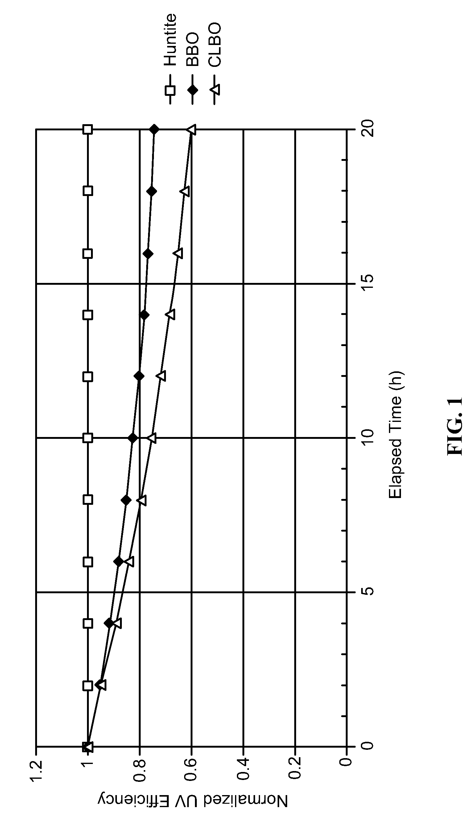
One of the most important factors that limit the usefulness of frequency-converted UV laser systems is the lifetime of NLO materials under conditions for UV production.
These NLO devices are unable to support long term, high-output UV light because of their intrinsic weakness in the presence of moisture.
Water reacts with the material's surfaces, and penetrates into its bulk, causing breakdown in high intensity laser beams.
Every method attempts to overcome the intrinsic faults of BBO and CLBO and resolve longevity issues of the UV NLO process, but with varying degrees of inadequate success.
A related consequence to the hygroscopic nature of BBO and CLBO: these NLO materials are limited in the degree to which they are able to support high intensity radiation.
With activation energy supplied by high intensity input beams, surface damage on the polished faces is quickly promoted in the presence of water.
As a result, conversion efficiencies remain well below optimum and device operational lifetimes are significantly compromised.
It has also been demonstrated that FC efficiency in NLO devices to generate UV light reaches a threshold where increased input intensity does not produce the expected UV output energy.
This condition is accounted for by a phenomenon of thermal dephasing where optical absorption within the NLO device leads to localized heating; this causes the refractive indices of the material to change with changing temperature and thereby disrupts optimal phase-matching conditions within the device.

Method used


Image

  • Method and apparatus for pulsed harmonic ultraviolet lasers
  • Method and apparatus for pulsed harmonic ultraviolet lasers
  • Method and apparatus for pulsed harmonic ultraviolet lasers

Examples


first embodiment

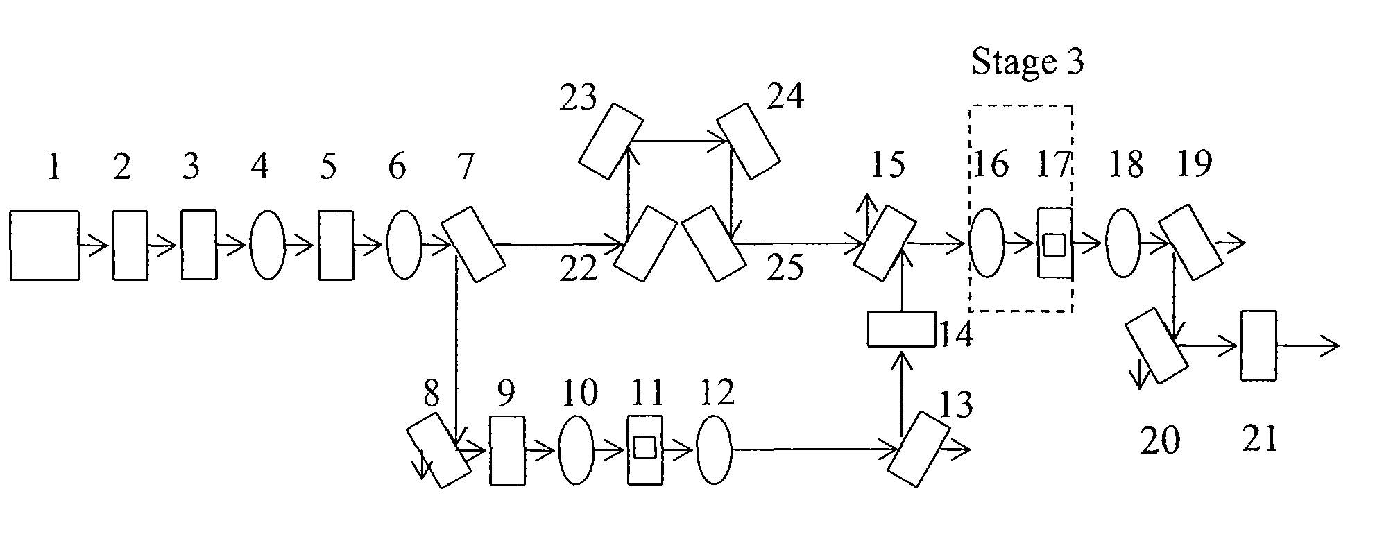
[0071]Embodiments of the present invention relate to an ultraviolet laser apparatus that includes one or more source lasers and one or more FC devices, where at least one such FC device is fabricated from a compositional member of the preferred materials; these constituents combine to operate as a system so as to produce QCW or pulsed UV light of 190-350 nm. In a first embodiment, the pulses from the source laser(s) have pulse durations between 1 ps and 300 ps, and the repetition rate is high enough (10 MHz to 1 GHz) to allow the output of the laser apparatus to be effectively continuous wave for a number of applications. In many instances these pulses are stretched by applying a linear chirp, the lengthened pulses are then intensified in preamplification and power amplification stages, and then compressed back down into in the low picosecond regime. This serves to increase the pulse peak power while maintaining QCW pulse repetition rates, so as to generate sufficient peak power to ...

second embodiment

[0072]In a second embodiment, a coherent pulsed UV light source with wavelengths that range between 190 and 350 nm is provided. The beam is made up of pulses of durations lying between 300 ps and 100 ns, having a pulse repetition rate of 100 kHz to 5 MHz. This pulsed laser design is comparable in average power to the QCW laser architecture, with the tradeoff being lower repetition rates for longer pulse durations.

third embodiment

[0073]In a third embodiment, for generation of higher pulse energies in pulses with durations of 1 ns to 1 μs, a specialized master-oscillator-power-amplifier source laser architecture is provided with a mode-locked seed laser and a uniform pulse rate that can be modulated to produce gated packets of pulses that are later amplified in a highly-saturated laser amplifier. By creating pulse packets that contain a plurality of shorter pulses, the laser design reduces the duty cycle over a non-modulated design, thereby boosting the pulse peak power and efficiency in subsequent FC stages.

[0074]Pulse packet repetition rates are typically 100 kHz to 100 MHz with intra-packet oscillator pulses of 10 MHz to 1 GHz. The source laser(s) used in the laser apparatus are designed to achieve peak powers typically greater than those used in frequency-converted lasers of prior art. When such a packeted pulse laser design is coupled with a UV FC stage that contains an NLO device made from the preferred...


PUM

PropertyMeasurementUnit
wavelengthaaaaaaaaaa
wavelengthsaaaaaaaaaa

Abstract

An apparatus for producing coherent, pulsed ultraviolet light with pulse durations that range between 1 ps and 1 μs includes one or more source lasers in the visible or near-infrared frequency range. The apparatus also includes one or more FC stages, at least one of the one or more FC stages including a nonlinear FC device and one or more optical elements. The optical elements include a reflector, a focusing element, a polarization-controlling optic, a wavelength separator, or a fiber optic component. The FC device includes a huntite-type aluminum double borate nonlinear optical material configured to produce FC light having a wavelength between 190 and 350 nm and a composition given by RAl3B4O12, where R comprises one or a plurality of elements {Sc, La, Y, Lu}. The nonlinear optical material is characterized by an optical transmission greater than 70% over the wavelength range of 190 to 350 nm.

Description

CROSS-REFERENCES TO RELATED APPLICATIONS[0001]The present application claims benefit under 35 U.S.C. §119(e) of U.S. Provisional Patent Application No. 60 / 953,402, filed on Aug. 1, 2007, entitled “Method and Apparatus for Quasi-Continuous Wave Harmonic Lasers” and U.S. Provisional Patent Application No. 60 / 975,804, filed on Sep. 27, 2007, entitled “Method and Apparatus for Pulsed Harmonic Ultraviolet Lasers,” the disclosures of which are hereby incorporated by reference in their entirety for all purposes.BACKGROUND OF THE INVENTION[0002]The present invention relates generally to high performance laser sources internally using nonlinear optical processes to convert laser light to greater frequencies. Merely by way of example, embodiments of the present invention provide an apparatus useful for generating coherent pulsed ultraviolet (UV) light with wavelengths that range between 190 and 350 nm, pulse durations that range between 1 ps and 300 ps, and 10 million or more pulses per secon...

Claims


Application Information

Patent Timeline
Patent Type & Authority Patents(United States)
IPC IPC(8): G02F1/35G02F2/02
CPCG02F1/3551G02F1/353G02F1/3532G02F1/3534H01L51/5203H10K50/805
Inventor ALEKEL, THEODOREDUTTON, DAVID A.FOSTER, DAVID H.LACHAPELLE, JOSEPH G.MUNROE, MICHAEL J.
Owner LADARSYST INC
Learn More