
Safe trampoline

Inactive Publication Date: 2016-06-16
PSKOREA +1
View PDF1 Cites 4 Cited by
  • Summary
  • Abstract
  • Description
  • Claims
  • Application Information

AI Technical Summary

Benefits of technology

The present invention helps maximize space by minimizing the gap between a resilient mat and a frame. This reduces the risk of injury from a spring tension space.

Problems solved by technology

However, a trampoline according to the related art may cause a space at a spring part connecting a resilient mat to a frame provided around the resilient mat, frequently causing a safety accident in which a foot drops through the space.
Accordingly, a supplementary measure using a high tension band has been tried, but the resiliency of the band deteriorates and a food of the user still drops down.
However, a problem of dropping a foot of the user may be solved by the cover suggested in the utility model document to a degree, but a space between an edge of the resilient mat covered by the cover and the frame cannot be used.
That is, an area for a jumping operation is restricted.

Method used


Image

  • Safe trampoline
  • Safe trampoline
  • Safe trampoline

Examples


first embodiment

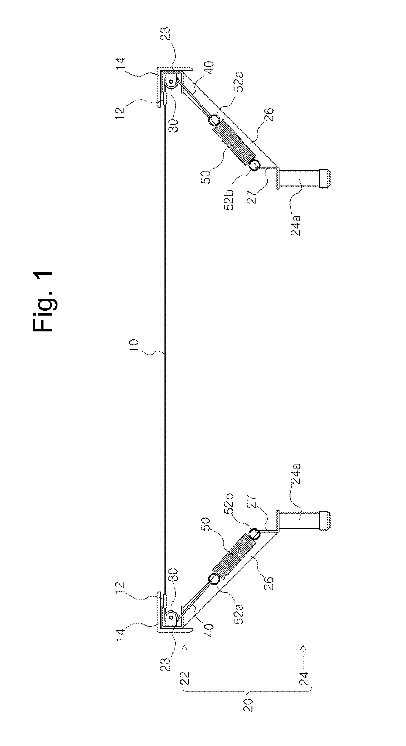
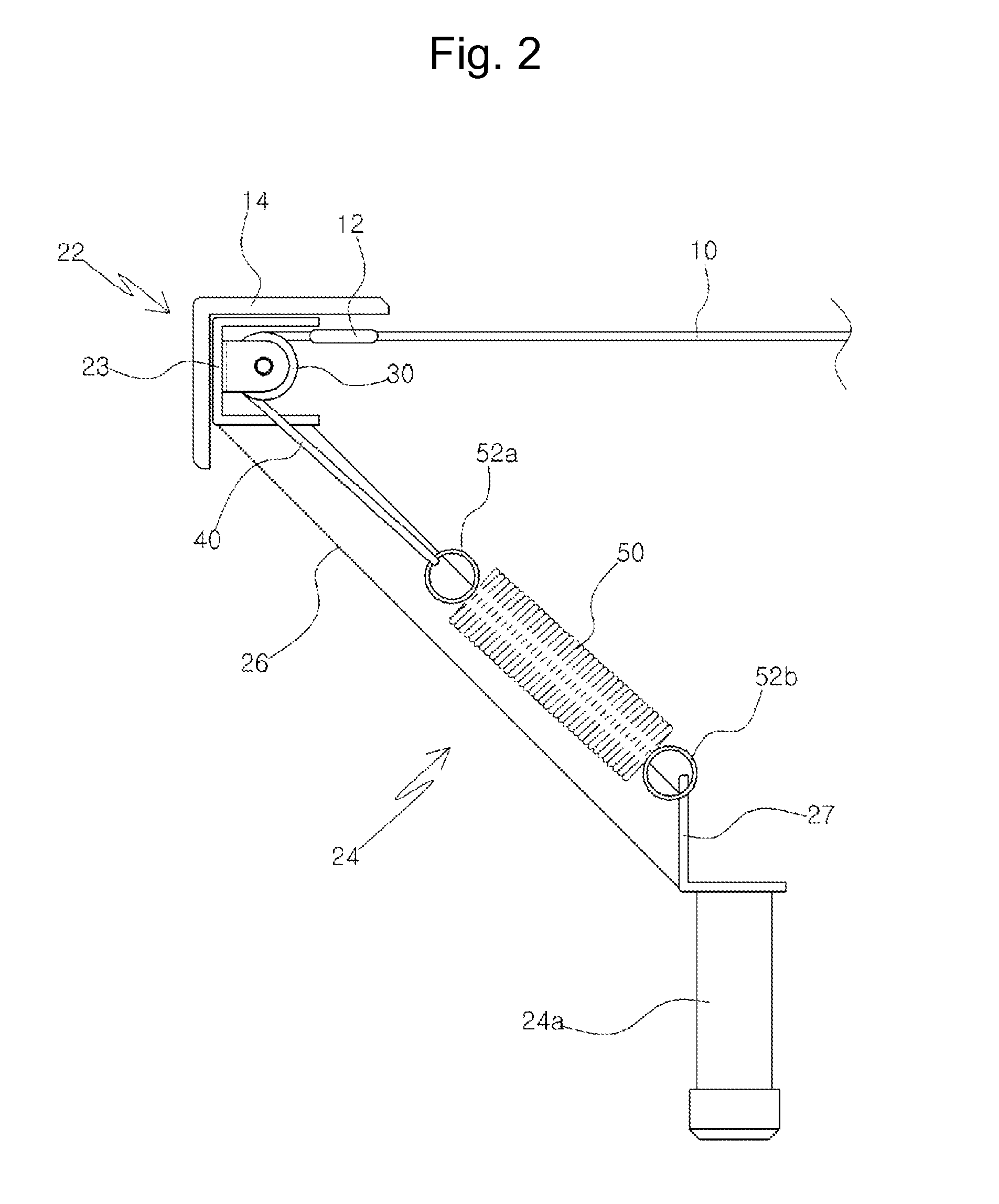
[0029]FIGS. 1 and 2 illustrate a trampoline according to the present invention.

[0030]Referring to FIGS. 1 and 2, the trampoline according to the first embodiment of the present invention includes a flat resilient mat 10, and a support frame 20 including an upper frame 22 formed around the resilient mat 10 and a lower frame 24 for supporting the upper frame 22.

[0031]In particular, as illustrated in FIG. 2, a plurality of rollers 30 are mounted on the upper frame 22 arranged on an upper side of the support frame 20.

[0032]Then, the roller 30 may be directly mounted on the upper frame 22, but it is preferable that the rollers 30 are mounted via a separate outer frame 23 provided in the upper frame 22 for fixing stability as illustrated.

[0033]In the first embodiment of the present invention, a plurality of connection hooks 12 are mounted at a periphery of the resilient mat 20, and sides of connection members 40 other than the springs are connected to the connection hooks 12, respectively...

second embodiment

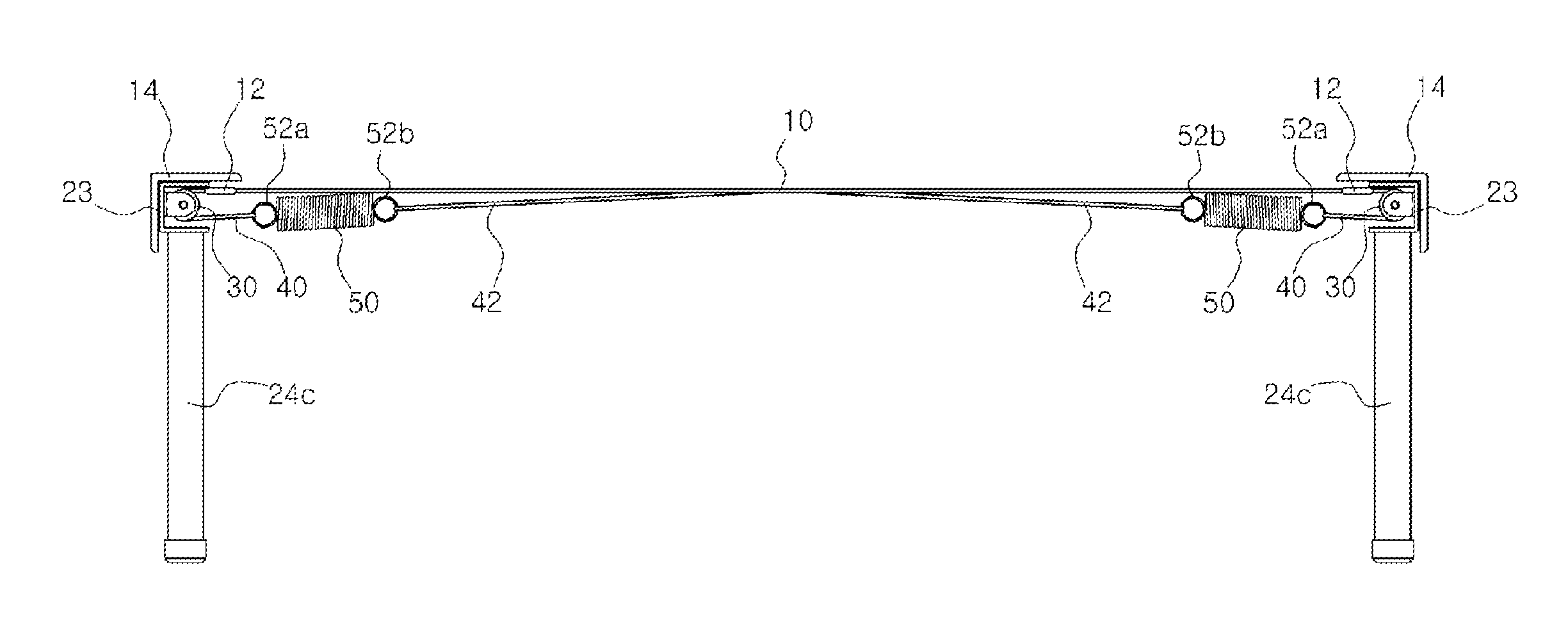
[0039]FIG. 3 illustrates a trampoline according to the present invention.

[0040]The trampoline according to the second embodiment of the present invention illustrated in FIG. 3 is the same as that of the first embodiment except for a management aspect of the resilient body 50. Accordingly, a description of the same parts will be omitted.

[0041]In the second embodiment of the present invention, sides of the resilient bodies 50 are coupled to the opposite sides of the connection members 40 and the opposite sides of the resilient bodies 50 are fixedly coupled to the lower frame 24, and the resilient bodies 50 are fixedly coupled substantially vertically with respect to the resilient mat 10. This form of trampoline is suitable for a business.

third embodiment

[0042]FIG. 4 illustrates a trampoline according to the present invention.

[0043]The trampoline according to the second embodiment of the present invention illustrated in FIG. 4 is the same as that of the second embodiment except for a management aspect of the resilient body 50. Accordingly, a description of the same parts will be omitted.

[0044]According to the first embodiment of the present invention, sides of the resilient bodies 50 are coupled to the opposite sides of the connection members 40, and the opposite sides of the resilient bodies 50 are fixedly coupled to a periphery of the resilient mat 10.


PUM


Abstract

A safe trampoline includes a flat resilient mat, and a support frame including an upper frame formed around the resilient mat and a lower frame for supporting the upper frame. The safe trampoline includes: a plurality of rollers mounted on the upper frame; connection members other than springs, sides of which are indirectly or directly coupled to a periphery of the resilient mat and opposite sides of which are partially wound on the rollers; and resilient bodies, sides of which are coupled to the opposite sides of the connection members and opposite sides of which are fixedly coupled to a specific part of a planar lower location of the resilient mat. The resilient bodies extend or are restored to the original positions according to a load applied to the resilient mat.

Description

TECHNICAL FIELD[0001]The present invention relates to a safe trampoline that employs a connection member such as a wire, chemical fibers, or a fabric band and a rotatable member such as a bearing.BACKGROUND ART[0002]In general, a trampoline is an exercise device in which a net or a resilient mat is connected to a steel frame having a predetermined shape by springs, and refers to an exercise device which the user can scale to jump therefrom. The trampoline is widely known to people as a public exercise device that contributes to treatment as well as exercise through a jumping operation.[0003]However, a trampoline according to the related art may cause a space at a spring part connecting a resilient mat to a frame provided around the resilient mat, frequently causing a safety accident in which a foot drops through the space.[0004]Accordingly, a supplementary measure using a high tension band has been tried, but the resiliency of the band deteriorates and a food of the user still drops...

Claims


Application Information

Patent Timeline
IPC IPC(8): A63B5/11A63B71/00
CPCA63B71/0054A63B5/11A63B21/02
Inventor CHOI, PIL SUN
Owner PSKOREA
Learn More